
Keywords: summary english friction pipelines multiphase carbon dioxide aeolian water production energy recovery
Seven themes are summarized in this section. They include 1- flow friction; 2 – pipelines; 3 – two-phase flows; 4 – carbon dioxide; 5 – wind power systems; 6 – water production and 7 – renewable energies.
Theme 1 – FLOW FRICTION
–
1.1-General information on fluidic friction
As the solid friction, resulting from the relative movement between two solid elements in contact, the fluidic friction, resulting from the relative movement between a solid element and a fluid, is of very great importance. This friction causes energy losses transformed into heat contributing twice to global warming (the losses themselves and the overconsumption of energy). This degraded energy is irrecoverable corresponding in thermodynamics to an increase in entropy. Fluid friction may be found, for instance, inside gas or liquid turbines driving electric generators or in gas or liquid pipelines which therefore require the use of large pressurizing stations. These two examples fall into the category of internal flows. It may also be found in means of transport like planes, trains, cars, trucks or boats. These latter examples fall into the category of external flows.
Given the importance of this fluidic friction, it is important to be able to predict it with sufficient accuracy in industrial applications (lift and drag of a wing or pressure drops in a pipeline), to determine the importance of tiny wall surface deformations (roughness, undulations), to characterize the surface of these walls (or coatings in contact with the flow), to develop measuring equipment to determine the hydraulic roughness (equivalent roughness on a fluidic basis) under all conditions of use, including the most severe (high density and high relative velocity of the fluid) also to develop techniques for reducing drag (in particular, reducing turbulent friction).
It is important to distinguish two fundamentally different cases of flow: a) laminar flow characterized by a low value of the Reynolds number (product of the volumetric mass by the hydraulic diameter, the relative velocity and the inverse of the viscosity). In this case, the relative velocity presents a parabolic profile while the flow is not very sensitive to surface deformations; b) turbulent flow characterized by a medium or high value of the Reynolds number. In this case, the relative velocity presents a relatively flat profile beyond a certain distance from the wall referred to as the boundary layer. This latest includes a very thin viscous layer in contact with the wall and a turbulent transition layer in between the viscous layer and the main turbulent zone.
_
1.2-Texture of a coated and an uncoated surface
The texture of a surface is extremely complex. It may be favourable or not to the displacement of a fluid. Fluid flow may be increased, relatively to a smooth surface, in the case of a turbulent flow and by using organised structures at the wall surface. On the contrary, it is reduced in the case of a turbulent flow and with walls covered by asperities distributed randomly (size and interval). Fluid flow is unchanged in the case of a laminar flow whether the surface deformations are distributed randomly or not.
Surface texture is the result of a manufacturing process, erosion, abrasion, corrosion or the application of a coating (internal in the case of a conduct). It can also evolve over time and according to the environmental conditions (physicochemical action). The texture of a coating depends on many factors: the material of the coating (epoxy, polyurethane), the mode of application (cold or deposition of molten particles), the size of pigments and fillers (solid particles), the type and concentration of a solvent (water, organic element).
Numerous industrial applications have made it possible to predict the surface topology of steels. Depending on the storage conditions, the operating time and the aggressiveness of the environment, it is possible to estimate the amplitude of the roughness. On this basis, the resulting friction factor may be roughly estimated.
The case of internal coatings is significantly different. The surface characteristics are very dependent on the type of coating and its mode of application. It should be mentioned that certain coating surfaces presents very small local roughness suggesting a favourable friction factor but also ripples of larger amplitudes with long wavelength which have been ignored for a long time by the industry but which could sometimes be very penalizing.
The surface characterization of a coating requires, therefore, the measurement of surface deformations using a sensor (often a roughness meter) from short to long wavelengths. The aerodynamic tests (presented below) make it possible to compare the results obtained in terms of hydraulic roughness (equivalent) and physical roughness.
_
1.3-Measurement of hydraulic roughness – Large boundary layer range
It is important to have a good understanding of the fluidic friction in a wall – fluid interaction in order to design industrial systems with the best possible precision. Fluidic friction is as well dependent on the wall material, in particular, its physicochemical properties as on the surface topology. It is also dependent on the physicochemical properties of the fluid as the flow conditions.
Determining experimentally, the characteristics of a low pressure and low velocity flow is relatively easy requiring low testing volume, short equilibrium time, small establishing length and low investment cost. It is quite different when it is desired to carry out tests with gases of high density, high pressure (up to 500 bar) or high velocity (up to 20 m / s) representing a very small boundary layer thickness. This results in high investment and operating costs.
To solve this problem, a relatively compact device has been developed which can induce a flow with a very small boundary layer thickness, of the order of a micron. It consists of a cylindrical vessel (external part) designed to withstand a pressure of 100 bars in which a cylinder (drum – internal part), driven externally by an electric motor, is rotated with a peripheral velocity of the order of 40 m / s. The internal cylinder drives the gas in its rotation which is then slowed down by a fixed wall mounted inside the high pressure vessel. The flow brakeage is measured using either a torque meter or a Pitot probe mounted in the air gap between the outside of the rotating cylinder and the inside of the fixed wall. A preliminary calibration phase with several fixed walls of different roughness makes it possible to determine (by interpolation) the equivalent roughness (hydraulic or aerodynamic) of any fixed wall.
The device has been used for testing the properties of pipeline internal coatings designed for gas transport. Tests have shown the occurrence of a wall sliding effect which appears, mainly, when the thickness of the boundary layer is very small (on the order of a micron meter).
http://yvcharron.com/index.php/coating-aerodynamic-testing/
_
1.4-Structured surfaces for turbulent friction reduction
It has long been believed that a rigid, straight, smooth surface was the optimum medium for minimizing the effects of turbulent friction, hence drag (hydraulic or aerodynamic) that is the friction factor. By observing the displacement of sharks into water, it was noticed that their relatively high velocity was due to the presence on their skin of micro asperities, oriented in the direction of their displacement and forming channels in the inter-space of the skin deformations. For this reason, these structures are commonly called “Riblets”.
Rectilinearly grooved surfaces – Two-dimensional or “2D” Shapes
Tests carried out in the mid-twentieth century on this type of surface structure showed that a reduction in hydraulic drag could be achieved within a range of 5 to 10% depending on the geometry of the groove (equilateral or half elliptical) or even, according to some experiments, between 10 and 12% (razor blade shape).
The explanation for these results relates to the following observations. In the case of a smooth surface, instabilities called “Low Speed Streaks” (kinds of longitudinal vortices, generally paired and rotating around themselves) develop near to the wall (at the limit of the viscous layer where viscous friction occurs) to occasionally burst from the boundary layer and amplify in size when escaping towards the flow core. This process is extremely dissipative. The use of micro grooves permits to control the “Low Speed Streaks” in their lateral displacement and to limit to some extend viscous dissipation near to the wall. The optimum size of the grooves corresponds approximately to the average diameter of the “Low Speed Streaks”. In this situation, these turbulent structures float on the tip of the solid structures explaining why the razor blade shaped grooves provide the best performance.
This physical explanation makes it possible to understand why the effect of the turbulent flow structures can be simulated with a RANS code (numerical simulation of fluids of the Reynolds Average Navier Stockes type), code in which the turbulence is modelled by equations and not simulated as in the case described below (three-dimensional structured surfaces). This code was used to verify the performance of grooves (solid structures) of different shapes (Triangular and knife blades) with several relative groove dimensions (width and height).
http://yvcharron.com/index.php/two-dimension-structures/
Sinusoidal grooved surfaces – Three-dimensional shape “3D1”
In turbulent flow, the energy dissipation is mainly of a turbulent nature and very little of a viscous nature. This turbulent dissipation represents a fraction of the order of 90% for slightly or moderately turbulent flows reaching 99.9% for very highly turbulent flows. These relative rates of turbulent dissipation provide some insight into the potential for energy gain offered by structured surfaces or any other means designed for turbulent friction reduction.
To this end, it should be noted the contribution of an oscillating transverse parietal movement characterized by a wall (a flat plate or the internal surface of a cylinder) in periodic transversal displacement (right – left) to the mean direction of the flow. For a given frequency, the energy gain is maximum. The energy input is globally positive (taking into account the energy required to oscillate the wall) for a given oscillation amplitude. The elongation and stabilization of Low Speed Streaks are two parameters put forward to explain the benefit of an oscillating transverse movement.
The combination of these two phenomena (rectilinear grooves and oscillating wall) has been used for the design of three-dimensional structured (grooved) surfaces. In this configuration, the grooves present a sinusoidal shape in direction of the flow. This concept was analyzed, not by using a numerical code of the RANS type but by using an LES code (Large Eddy Simulation) where the effect of turbulence is simulated and not modelled. The properties of turbulence are not calculated at the smallest scale (called Kolmogorov – DNS code) but at a larger scale related to the phenomenon to be analyzed. This code allows taking into account the deformation generated on the Low Speed Streaks by the oscillating movement. The code was first validated on linear grooves then used to determine the effect of a sinusoidal motion (amplitude and frequency) applied to the basic groove shape (linear). Under optimal conditions, the reduction in turbulent friction is of the order of 20%, which is roughly the double of the previous case.
http://yvcharron.com/index.php/three-dimension-structured-surfaces-type-1/
Grooved surfaces with two orthogonal transverse waves – three-dimensional shape “3D2”
The three-dimensional shape “3D1” corresponds to grooves of constant dimensions (width and height) in the flow direction and with a sinusoidal course oriented successively towards the left and the right respectively to the wall or the mean direction of the flow.
The three-dimensional shape “3D2” is similar to the shape “3D1” but with the addition of a sinusoidal displacement of the flow oriented successively upwards and downwards with respect to the wall and to the mean direction of the flow. The two waves such oriented are said to be orthogonal.
The three-dimensional shape “3D2” provides additional advantages compared to the shape “3D1”: a) additional stabilization and additional elongation of the Low Speed Streak (LSS); b) more viscous loss reduction at the wall surface; c) less frequent burst of the LSS towards the central core. In this “3D2” case, the wave normal to the wall is materialized by an increase in height of the grooves at the peak amplitude of the horizontal wave and a decrease in height of the grooves at the inflection point of the horizontal wave.
First calculations have shown a reduction in turbulent friction of more than 25%.
http://yvcharron.com/index.php/three-dimension-structures-type-2/
_
1.5-Deformable or porous coatings and injection of materials
A reduction in turbulent friction can be obtained in a conduct (pipeline) based on the mechanical properties and the constitution of the wall in contact with the flow.
A deformable coating providing an efficient reduction in turbulent friction relies on an optimum attenuation of pressure waves. In such a case, a pressure wave directed towards the wall generates a second wave in phase opposition that counteracts the action of other waves directed towards the wall.
A porous and permeable coating providing an efficient reduction in turbulent friction relies on an optimum attenuation of the velocity waves. The principle is similar to the previous case: a velocity wave directed towards the wall generates a second wave in phase opposition which counteracts the action of other waves directed towards the wall.
A reduction in turbulent friction can be achieved by injecting liquids or particles into the flow.
Film-forming agents injected into a flow (more generally gaseous) produce a reduction in aerodynamic drag on a plate in contact with this flow or a reduction in pressure drops inside a pipeline. The action of these agents which are deposited on a wall can be explained in several manners. It may be caused either by a parietal sliding resulting by a kind of sliding of the agents deposited along the wall (reduction in the relative velocity of the flow with respect to the wall) or a molecular force, normal to the wall, repelling the molecules of the fluid from the wall thus causing less brakeage by the wall.
Viscoelastic agents injected into a flow (more generally liquid) produce a reduction in pressure losses inside a pipe by a damping effect of the large turbulence structures in the flow core. The reduction in pressure drop can reach 75% in certain situations to the detriment of the particularly high injection cost of these agents.
_
1.6-Parietal slip
We can distinguish at least two different cases of parietal sliding.
The first case concerns the chemical compositions of the wall and of the moving fluid and the resulting molecular interaction between these two. Let’s consider the molecular forces normal to the wall. In the case of a force directed from the wall towards the flow core, the molecules of the fluid are so much less slowed down by the wall as they are more repelled by it. This results in an increase in the flow velocity which may be designated by “Wall slip”. In the opposite case, the result is a reduction in the flow velocity which may be designated as a “Wall brake”. Wall slip and wall brake are characterized by a “slip length” measuring the distance between the physical wall and the zero velocity condition (after extrapolation of the velocity profile).
The second case relates to the movement of movable walls within a fixed wall (for example, a conduct or a pipeline).
Let us imagine, firstly, a fluid not circulating by itself in a conduct but a fluid confined in sealed containers (caissons) moving along the conduct. In this situation, the pressure drop is limited to the viscous and turbulent losses produced between the fixed wall (conduct) and the moving one (container), i.e. over a very short distance (difference in diameter of the conduct and the container). These losses being very small, the result is a very low pressure drop along the conduct.
Let us imagine, secondly a mobile wall, rigorously circular, moving inside a fixed wall (pipeline), also rigorously circular and with a diameter slightly greater than that of the mobile wall. In this situation, there are two relative displacements, that of the mobile wall relative to the fixed wall and that of the flow inside the mobile wall. The energy loss corresponding to the mobile wall is very low given the small distance between the two walls and the lower relative velocity of the mobile wall compared to a free flow in a fixed pipe. The same is true for the pressure drop of the flow inside the moving wall, the pressure drop being proportional to the square of the velocity.
Let us imagine, thirdly, a somewhat more realistic situation concerning the materials used. Its principle, intermediate between the two preceding cases, would be as follows. A flexible material is produced in situ or deployed upstream of the pipeline in the form of thin and flexible strips or bands, parallel to the wall of the pipe and entrained by a sort of shield located downstream and pushed by the fluid. This system is reproduced along the pipe as many times as required by the length of the pipeline and the length of the band – shield system. A complex flow of fluid is established in which the fluid is predominantly enclosed within the straps (bands), therefore, with very little movement relative to them. The turbulence inside the bands is almost non-existent while the turbulence external to the bands evolves over very short distances being also largely attenuated by the flexible bands.
_
Theme 2 – PIPELINES
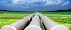
2.1-General information on pipelines
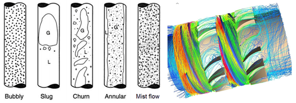
Pipeline design and operation involve many sciences or specialties and among them metallurgy, chemistry, geophysics, civil engineering, fluid mechanics, geopolitics and economics. The problems encountered are numerous and of different kinds. In metallurgy, the subjects are related to the quality and composition of steels to provide enough resistance to pressure, temperature, depressurization and corrosion. In chemistry, the preoccupation is related to the protection against corrosion (and associated control systems), in particular, with the use of internal and external coatings but also by the various causes of clogging (formation of hydrates or paraffin). Geophysics and civil engineering are concerned with the behaviour of pipelines on their land or sea support. Fluid mechanics deal with hydraulic aspects including various types of two phase flow (from liquid bubbles to plugs, liquid accumulation) or various aerodynamic and hydraulic aspects determining the sizing of pipelines, compressor stations and terminal design. Geopolitics is involved in the pipeline routing regarding customer locations and frontiers. Economics is essential since it determines the feasibility of a project for investors.
In this topic, we are particularly interested in some aspects relating to fluid mechanics: the use of specific internal coatings, the impact of the aging of internal coatings on the transmission factor, the degree of pressure loss linked to external welds with penetration inside a pipeline, a monitoring device for the continuous measurement of internal hydraulic roughness along a pipeline as well as the benefit of aerodynamic drag reduction techniques.
_
2.2-Aging of pipe internal coatings
Theme 1 on “fluidic friction” focuses more particularly on the surface characterization (roughness and undulations) of newly applied internal coatings as well as their aerodynamic performance measured with an aerodynamic test device called the “Rotating cylinder Unit” (RCU).
Theme 2 on “pipelines” focuses on aged coatings, that is, coatings subjected to the various operating conditions of a production system to determine the impact on their aerodynamic performance. The aging conditions studied relate, in particular, to erosion, to a sudden decompression and to the physicochemical interactions between internal coatings and certain chemical agents encountered in gas transport, for instance, tri-ethylene glycol. Sometimes, tests show a sharp deterioration in the aerodynamic performance for certain coatings even when their surface topology has not been altered. This aerodynamic behaviour is apparently the result of a physicochemical interaction between the chemical agent and the coating material. In this situation, the degradation of performance can be interpreted by a “molecular brakeage” of the wall (the reverse of a wall slip). See “Parietal slip” in theme 1.
_
2.3-Impact of welds on gas transport
Welds carried out on the outside of a tube or a pipeline can penetrate inside them with a greater or lesser impact depending on the characteristics of the weld (penetration height and routing inside a pipeline) as well as the flow most often represented by a Reynolds number. The higher this number (density, pressure and fluid velocity), the greater the pressure drops. On the contrary, the smaller this number, the more the pressure drops can be neglected.
To this end, it is necessary to distinguish three types of welding associated to three mechanical requirements corresponding each one to a specific shape.
Longitudinal welds result from the manufacturing of forged tubes, rolled and then welded along a longitudinal direction. This weld, although very long, has no effect on gas transport since it is in perfect alignment with the main flow. The height of penetration also has very little impact on pressure drops.
Radial welds met at regular intervals (generally every 12 m) are required for the assembly of tubes for the construction of a pipeline. Perpendicular to the flow, this type of weld partially obstructs the flow. The magnitude of the corresponding pressure loss is of the order of a few per cent. Magnitude of the pressure loss is determined, primarily, by the weld penetration height and by the thickness of the boundary layer, itself determined by flow conditions (primarily, the Reynolds number). Calculations were made using a RANS (Reynolds Average Navier Stockes) fluid mechanics code for several weld heights and shapes (semi-circular, elongated) and also several flow conditions.
Spiral welds are encountered during the manufacturing of tube sections of great length (18 to 24 m) and large diameter with a relatively low operating pressure (of the order of 100 bars). These tubes are made from coiled plates. This method of manufacture allows the production of tubes at a relatively low cost. Intermediate between the longitudinal weld and the radial weld, the pressure drop associated to a spiral weld is strongly dependent on the helix angle (spiral shape) but also on the penetration height inside the tube and the thickness of the boundary layer. The calculation of the pressure drop is particularly complex since it is necessary to perform flow simulations on asymmetric pipe sections and over great lengths. Calculations were made using RANS code for several weld heights and shapes, multiple helix angles and for various flow conditions.
http://yvcharron.com/index.php/internal-pipeline-welds/
_
2.4-Realization of structured surfaces inside a long tube
The benefit of structured surfaces has been presented in Theme 1 and, in more detail, in the case of three geometrical shapes: a) a two-dimensional; b) a three-dimensional “type 1” characterized by a transverse sine wave parallel to the wall and c) very succinctly, a three-dimensional “type 2” characterized by two transverse sinusoidal waves, one of which being parallel and the other orthogonal to the wall.
Achieving structured surfaces on a flat surface or inside a cylinder (for example, a pipeline tube) can be accomplished in several ways. In the case of structures of large dimensions (of the order of a millimetre) and for a limited surface, it is possible to produce them mechanically. In the case of structures with a small dimension (few tens of micron) to be produced on large surfaces, another method should be selected. The method adopted in this document comprises three stages.
In a first step, structured surfaces are produced with a great accuracy by using a femto second laser on a relatively rigid surface (surface erosion by laser ablation). These lasers allow the production of regularly shaped grooves in a periodic transverse movement (3D-Type1) and with a periodically adjustable depth (3D-Type2).
In a second step, it is proceeded to the manufacture of a flexible mould on the eroded (ablated) surface mentioned above. The structures of the flexible part are, practically, the mirror image of the structures provided by laser ablation.
In a third step, the flexible part mentioned above is applied shortly afterwards an internal coating has been applied on the internal surface of a tube. After the time required for the coating to harden, the flexible part is removed. The structures inside the tube are practically identical to those made in the first step.
_
2.5-Measurement of hydraulic parameters inside a pipeline
Devices are sometimes introduced inside pipelines during maintenance operations. These devices are divided into two main categories: mechanical pigs which essentially aim to carry out cleaning inside a pipeline (displacement or removal of paraffin deposits or liquid plugs). These pigs are strictly passive. There is a second category, the purpose of which being to perform measurements such as the wall thickness of the pipeline to assess the effects of corrosion and adapt the flow rate and frequency of injection of anticorrosion products. These pigs are equipped with electronics, batteries, transmitters and various sensors. They are said to be “Intelligent Monitoring Pig” or “Smart Monitoring Pig“.
It is proposed in this section another type of “Smart Monitoring Pig” whose objective is to continuously measure the hydraulic roughness along the entire length of a pipeline. The device is inspired by the operation of the “Rotating Cylinder Unit” described in Theme 1 (Fluidic friction). The device operates as follows: A cylinder is rotated with the aid of an electric motor near the wall of the pipeline. A Pitot tube installed in the air gap between the cylinder and the wall measures the velocity of the intermediate gas. From this measurement it is possible to interpolate the hydraulic roughness from a calibration curve (established following a calibration phase with defined roughness) which is then stored in a digital device. The measurement can also be done at several transverse angles (North, South, East, West or intermediate).
Associated to pressure and temperature measurements, the knowledge of the hydraulic roughness would provide a detailed survey of corrosion and material deposit zones along the pipeline.
http://yvcharron.com/index.php/pipeline-pig-monitoring/
_
2.6-Technico economical studies
The cost of a pipeline depends on a very large number of parameters, starting with the characteristics of the fluid transported. It also depends on the quality of the steel, the diameter and the design pressure of the pipeline as well as the compression stations (including intermediate stations for pipeline of several thousands of kilometres). All these parameters are, of course, interrelated requiring in some cases some compromise.
As the investment cost is considerable, it is important to minimize the pressure drop. For a pipeline in a given configuration, a reduction in pressure losses can be obtained in different ways with sometimes high performance associated with a technological complexity.
To facilitate understanding of the technical – economic study, a few technical elements are recalled below. For a pipe of given diameter and a fluid of given viscosity, the thickness of the boundary layer (approximately 5 times the thickness of the viscous layer) is inversely proportional to the density (for a gas, product of the molecular mass by the absolute pressure and the inverse of the absolute temperature) and also the fluid velocity. This thickness is also an inverse function of the Reynolds number. The friction factor is a decreasing function of the Reynolds number up to a threshold value where it is substantially determined by the relative roughness. Pressure losses are proportional to the friction factor, the square of the fluid velocity, the volumetric mass (or density), the length of the pipeline and the inverse of the diameter. For a given mass flow rate, the pressure drop varies with the inverse of the diameter to the power of 5.
Pipeline uncoated internally: the internal roughness of the pipeline increases significantly over time. If the Reynolds number is low (thick boundary layer), the pressure drop is not significantly dependent on the roughness magnitude. Beyond a certain Reynolds number, the pressure drop becomes relatively large.
Internally coated pipeline: By applying an internal coating with a thickness approaching one hundred microns, it greatly reduces the internal roughness of the pipeline. This value is maintained at a relatively low level for several tens of years of operation. This solution makes it possible to greatly reduce the pressure drop compared to an uncoated pipe.
Pipeline coated internally with smoothing of the coating before coating hardening (see corresponding section). This procedure allows a further reduction in the friction factor when the boundary layer is thin (large value of the velocity and pressure product that is high Reynolds number).
Pipeline coated internally with 2D structuring (see corresponding sections: 2D application and performance) of the coating before curing. This procedure allows a reduction in the friction factor of around 8% compared to a strictly smooth surface, regardless of the thickness of the boundary layer. This method is easier to implement for an average dimension of structures greater than 50 microns (average thickness of the boundary layer). Note that for water transport, the average dimension of structures is of the order of 100 microns.
Pipeline coated internally with 3D structuring (see corresponding sections) of the coating before curing. This procedure allows an additional reduction in the friction factor of around 16% compared to a strictly smooth surface, regardless of the thickness of the boundary layer. As in the previous section, this method is easier to set up for an average dimension of structures greater than 50 microns. The realization of a structured surface is slightly more expensive than that of a smooth surface concerning the realization of the primary moulds.
These technical elements make it possible to choose the type and method of application of an internal coating, the operating pressure, the average diameter of the pipeline, the size and the distance between the compression stations within the framework of economic optimization.
_
Theme 3 – TWO PHASE FLOW
–
3.1-Two-phase compression – pumping
The multiphase limits of single-phase compression and pumping equipment
Single-phase compression expression is used to mean the compression of a gas phase (compressible) and single-phase pumping to mean the pumping of a liquid phase (incompressible). Hereinafter, the term compression or pumping is used indifferently when it concerns a two-phase mixture.
The equipment required for single-phase compression or pumping is of the volumetric type (pistons, gears, diaphragms) or of the rotodynamic part. In the first case, the energy transmitted by the pressurizing machine is directly converted into pressure. These machines present many advantages including efficiency and the ability to compress a two-phase phase with a relatively high “efficacy” (this parameter measures the ratio between efficiencies, respectively, in two-phase and single-phase flows). These machines, on the other hand, are heavy, bulky and require significant maintenance. In the second case, the energy transmitted by the pressurizing machine is, firstly, converted into velocity (through a rotating wheel or impeller) then into pressure (through a fixed diffuser or rectifier). These machines present many advantages in terms of pressure (radial machines) and volume flow (axial machines), reduced space and limited maintenance. On the other hand, the efficiency is largely dependent on the volume flow. Furthermore, these machines are totally unsuitable for two-phase compression or pumping, whether in the presence of a small quantity of liquid associated with a gas phase (erosion is an additional drawback) or of a small quantity of gas associated with a liquid phase (gas plug at the entrance a radial wheel). Beyond a very low level of gas (for a pump) or liquid (for a compressor), the two-phase efficacy tends towards zero.
Helico – axial hydraulics – Poseidon type – 1st generation hydraulic
To overcome the inability of conventional rotodynamic machines to compress or to pump two-phase effluents, IFP has developed in the eighties a helico axial hydraulic system called “Poseidon”. The impeller (the wheel) includes vanes with a very small entry angle (often less than 10 degrees) and a very small curvature. These blades are therefore relatively long (overlap ratio between 1.5 and 2.0) generating relatively high viscous losses. According to this design, the accelerations in the longitudinal, transverse and radial directions are relatively low. These characteristics are obtained by a small variation of the passage section (the area) along the flow path, a small blade curvature and the action of a Coriolis force in the radial direction reducing the effect of the centrifugal force. For a low or high gas- liquid volume flow ratio represented by the GLR parameter (for “Gas – Liquid Ratio”), the two-phase efficacy is close to 1. On the other hand, for an intermediate GLR (between 2 and 10 depending on the geometry), the efficacy decreases significantly when the GLDR parameter (for “Gas – Liquid Density Ratio”) is reduced.
In conclusion – Despite relatively good performance compared to single-phase machines, Poseidon hydraulics present several drawbacks: significant viscous losses and low two-phase efficacy at intermediate GLR’s.
Helico – axial hydraulics with interfacial slip control – 2nd generation hydraulic
The operation of the Poseidon hydraulics is satisfactory at low GLRs, the low orthogonal accelerations (longitudinal, transverse and radial) limiting to some extend the separation of the phases in the three main directions. Beyond a certain GLR (for example 2 – value dependent on many parameters including pressure, viscosity and surface tension), the two phases separate, generating strong interfacial losses. In strictly helico-axial hydraulics, the liquid phase is projected against the surface with the larger diameter slowing it down in its displacement towards the outlet (relatively large viscous forces) which in turn induces a braking of the gaseous phase (high energy dissipation at the interface of the two phases). The difference in velocity between the two phases is referred to as the interfacial slip. The parietal braking of the liquid film increases with a decrease of the liquid film thickness.
To remedy this situation, the external part of the impeller (larger diameter) is tuned to provide it with a very slight radial shape including, at the inlet, a convex curvature (centre of the curvature directed outwards) allowing a large acceleration of the liquid phase and, at the outlet, a concave curvature (centre inward) allowing a reduction in the acceleration of the liquid phase. These two curvatures help to minimize the velocity difference between the two phases. This action is referred to as “interfacial slip control”. This action allows a relatively large increase in the two-phase efficacy for any value of GLR, including, for low values of the GLDR parameter.
The control of the interfacial slip allows a certain “relaxation” of the impeller blade parameters. In particular, the blade length may be reduced (smaller overlap ratio) limiting viscous losses, thus, providing higher single and two phase efficiencies. In addition the blade curvature may be increased, consequently, providing a greater manometric head coefficient (compression ratio).
In conclusion – This second-generation hydraulic system presents, compared to the first-generation, in single phase flow, a higher efficiency and a higher manometric head coefficient as well as a higher two-phase efficacy.
Radio – helico – axial hydraulics – Wet gas
The design of hydraulics suitable for compressing wet gas derives from the design of the second generation helico axial hydraulics.
The terminology “wet gas” denotes a low level of liquid fraction within the gas phase corresponding to a significant braking of the liquid film along the surface with the larger diameter. As a result, the external curvatures located, respectively, at the inlet and at the outlet of the impeller are accentuated so as to greatly accelerate the liquid film (small thickness) towards the outlet.
This configuration results in a diameter significantly increased at the outlet, compared to the inlet, providing a more radial shape of the impeller. This configuration presents two advantages: less droplet erosion at the impeller inlet and a higher manometric head coefficient which is required in the case of the compression of a gas with a lower volumetric mass compared to a two phase flow with medium GLR.
Helico – radio – axial hydraulics – Bubbly flow and viscous liquid
In bubbly flow (very low GLR), separation forces (accelerations acting in the three main orthogonal directions) have a lesser effect compared to the drag forces acting on bubbles submerged in the liquid phase.
As the separation forces get smaller, it is possible to apply a certain “relaxation” on the design parameters defining the 1st generation hydraulic (Poseidon). It is, in particular, possible to design a hydraulic with a more radial shape (Helico radio axial), to shorten the length of the blades and to bend them so as to increase as well the efficiency as the manometric head coefficient of an impeller.
In the presence of a viscous liquid, the drag forces acting on the bubbles increase further compared to a situation with a non-viscous liquid. As a result, it is possible to apply a greater “relaxation” on the design parameters of the 1st generation hydraulic.
http://yvcharron.com/index.php/two-phase-flow-pumps/
_
3.2-Two-phase expansion – turbines
The multiphase limits of single phase expansion or turbine equipment
By single-phase expansion it is meant here the expansion of a gaseous phase (compressible) through an expander and by single-phase depressurization, the let-down of a liquid phase (incompressible) through a turbine. These expansions or let downs result in energy supply.
It is generally easier to depressurize, with a single-phase equipment, a slightly two-phase mixture (low or high GLR) than to pressurize it. However, these depressurizations generally take place through a single stage.
The challenge is to design a two-phase multi-stage turbine so as to respond to a high expansion rate.
Helico – axial hydraulics – 1st generation
According to a simplified approach, an expansion impeller (wheel) of a two-phase multistage turbine looks similar to a compression impeller of a two-phase multistage pump, the inlet section of the compression impeller acting as the outlet section of the expansion impeller. The same principle goes for the opposite sections. The same principle goes also for the static elements (diffuser and inducer). However, the outlet angle of the expansion inducer is significantly reduced compared to the inlet angle of the compression diffuser.
This hydraulic expansion provides advantages similar to those of the pumping one.
Helical – axial hydraulics – 2nd generation
The control of the interfacial slip in the wheel of a two phase turbine is similarly carried out to the control described for a compression system. It provides a significant improvement in both single and two-phase performance.
Radio – helical – axial hydraulics – Bubbly flow and viscous liquid
Consideration of the interfacial slip as well as the ratio of the forces of separation and drag of the bubbles in the liquid leads to the same conclusions as those made in the context of a compression or pumping system.
http://yvcharron.com/index.php/two-phase-flow-turbines/
_
3.3-Two-phase pump and pipeline interaction
The accumulation of gas in a liquid pipeline leads to an increase in pressure drop along the pipeline requiring either an increase in the upstream pressure or a decrease in the downstream pressure. This gas fraction increase also induces hydrodynamic instabilities that can cause some damage to the overall system or at least some interruption in the flow production. It should be noted that increasing the upstream pressure often leads to a reduction in the flow rate and that lowering downstream production is usually only possible within a narrow interval.
The installation of a multiphase pump facilitates the transport of the multiphase flow (an increase in the flow rate) while maintaining the upstream and downstream pressures in their earlier conditions (very low gas fraction). In addition, the use of a multiphase pump permits a significant reduction in hydrodynamic instabilities improving the overall performance and availability of the system.
In a marine configuration, a multiphase flow pump may be mounted on “Topside” or “subsea” but also in the upstream or downstream parts of the system. A hydrodynamic study permits to establish the best solution between these four options.
http://yvcharron.com/index.php/pipeline-pump-interaction/
_
3.4-Petroleum and para-petroleum applications
There are a very large number of applications for two-phase pumping. In general, each time the gas and liquid phases are separated upstream the pressurization phase then re-mix downstream, it is possible to replace the entire system (separation, piping, cooling system for the compression unit as well as compressors and pumps and their allocated drive) by a single two-phase pump (compressor) and its drive mean. The same goes for a two-phase expansion where all of the single-phase expansion means (separation, piping, expander and turbine) can be replaced by a single two-phase turbine with its own energy supply (electric generator or any type of turbo machine).
Regarding two-phase pumping-compression systems, we can mention:
Marine production of auxiliary fields linked to a central production platform or to a land terminal. These auxiliary pumps can be surface mounted or submerged. These systems are particularly attractive requiring only a single production pipeline and no separation system downstream of the wellhead.
Stabilization of a two phase flow (reduction of hydrodynamic instabilities) in a pipeline between the production and the delivery points – See the previous section “Two-phase pump and pipeline interaction”.
The simultaneous production of high and low pressure wells. Usually, for the transfer of the production from wells with different pressure levels, it is necessary to significantly lower the pressure of the high pressure wells to allow production of the low pressure wells. By recovering energy from a high pressure well via a two-phase turbine and transmitting it to a low pressure well via a two-phase pump, the pressure downstream of the turbo pump system is intermediate between those of the HP and BP wells thus allowing a greater production from all the wells.
Concerning petrochemical applications, the examples are too numerous to be cited here.
Regarding two-phase expansion systems, we can quote:
Electricity production; Refrigeration loops with replacement of Joule – Thompson valves by two-phase turbines; LNG production; Stabilization of condensates; Simultaneous production of high and low pressure wells (See multiphase pumping systems) and Gas treatment.
_
Theme 4 – CARBON DIOXIDE
Dioxyde de carbone – Gas turbines, boilers, vehicle engines; Pressurization and expansion loop, capture, compression, transport and injection; Energy recovery; Acid gases; Geothermal loop
–
4.1-General information on carbon dioxide
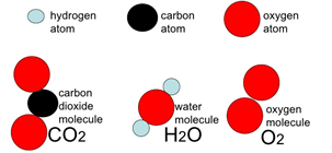
In this chapter, we are particularly interested in carbon dioxide, but also in sulphur and nitrogen oxides that are often associated with it. These gases are sometimes referred to, in the presence of water, by “acid gases” because of their aggressiveness towards materials. These gases often result from the combustion of carbonated materials or fossil fuel such as carbon dioxide and nitrogen oxides (also called NOx). Carbon dioxide is also produced during the extraction of fossil fuels sometimes in association with hydrogen sulphide.
These gases are dangerous or harmful to the health of living beings and to the environment. It is therefore necessary either to limit their production rate (improvement of energy efficiency) or to capture them during their extraction or their production during a chemical transformation (combustion of carbon elements).
Following the extraction of fossil fuels, carbon dioxide and hydrogen sulphide are separated from hydrocarbons by physicochemical processes. In the case of hydrogen sulphide, this gas is sometimes transformed into sulphur. Carbon dioxide is sometimes used by the food industry or reinjected into the ground either to enhance the production of oils (hydrocarbons in liquid form) by increasing the pressure of the reservoir or for long-term storage. They can also be injected into depleted reservoirs comprising an aqueous phase allowing the dissolution of acid gases in water.
During the refining of hydrocarbons, the sulphur fraction is considerably reduced so as to limit the emissions of sulphur oxides into the atmosphere during the combustion of mainly heavy fuels.
The combustion of hydrocarbons generates carbon dioxide, an essential molecule in the process of energy or heat production. With fossil fuel engines, the higher is the production of carbon dioxide (hence, the lower the production of carbon monoxide), the higher the efficiency of energy production. The combustion of hydrocarbons also generates nitrogen oxides, the rate of which depends mainly on the combustion temperature and the transit time in the combustion chambers. There are several ways to limit the level of NOx during combustion.
The rate of production of carbon dioxide per mass unit of fuel or energy unit depends on the constitution of carbon molecules, in the sense that the more a carbonated molecule contains hydrogen atoms the more this molecule is energetic for a given mass. Thus, the combustion of a methane molecule (CH4) is relatively more energetic than that of ethane (C2H6) which is itself more energetic, successively, than those of propane (C3H8), butane (C4H10), pentane, hexane, etc. For this same reason, a gasoline is more energetic than a diesel fuel (diesel engine), the C8 chains of an average gasoline containing relatively more hydrogen atoms than the C13 chains of an average gas oil. The energy efficiency of a fuel should not be confused here with the combustion efficiency of an engine. Thus, a diesel engine is more efficient than a gasoline engine because of the combustion temperature which is higher in the first case than in the second and not because of the fuel quality.
This chapter presents five situations related to carbon dioxide: a) Large power plants (electricity) based on the combustion of fossil fuels, b) Means of transport using energy produced from fossil fuels; c) The combined reinjection of acid gases and an aqueous phase in an aquifer; d) The operating principle of a closed geothermal loop operated with carbon dioxide for the production of energy and heat; e) Problems that may be encountered when compressing carbon dioxide
–
4.2-Fossil fuel power stations – Carbon dioxide captation by a physical solvent with energy recovery
Large power plants provide electricity from nuclear fuels, coal or hydrocarbons with the use of electric generators driven by steam or gas turbines. These fuels provide respective advantages and disadvantages. In the three above cases, the thermal efficiency is relatively small (well below 50%) characterized by the rejection of a very large amount of heat, not converted in energy, into the atmosphere. In addition, in the case of coal and hydrocarbons, several types of pollutants are released into the atmosphere, the main one being carbon dioxide.
The document deals with the case of gas turbines proposing some solutions for both improving the thermal efficiency of the energy production unit and allowing the capture of acid gases, in particular, carbon dioxide and nitrogen oxides. In the basic case, carbon dioxide is captured at high pressure using a physical solvent in a compression-expansion loop. These solutions could also be suitable in the case of combustion of coal from a boiler producing steam at high temperature and high pressure.
In the environmental crisis that we are currently experiencing, it should be noted that the combustion of carbon-based material would constitute a hope and not a handicap if we facilitated the production of gasoline and diesel from biomass and if we combined it to the system described in this document. As such, in a first step, biomass production would be focused on materials with a high growth rate (high carbon dioxide absorption rate) while, in a second step, carbon dioxide would be captured downstream the combustion (exhaust gas). Unlike the current situation where the concentration of carbon dioxide in the atmosphere is increasing by the combustion of fossil fuels and the lack of capture of this gas, we would go towards a decrease in this gas concentration with an increase in energy production.
–
4.3-Fossil fuel vehicle engines – Energy recovery and carbon dioxide captation
The previous section deals with large scale fossil fuel stationary power plants. In these land-based installations, it is possible to deploy large and complex energy recovery means (heating of buildings, steam production but also the use of a Rankine cycle or a combined cycle) as well as capture of carbon dioxide (from chemical or physical solvents) as well as the compression, the export, the injection and the storage of toxic gases produced during combustion.
For mobile energy production units (land or sea application), energy recovery and acid gas treatment conditions are much less easy, requiring resources adapted to the situation.
In the 21st century, environmental pollution (greenhouse effect, emissions of fine particles) is such that electric vehicles are seen as the main solution to solve the growing demand for means of transport. However, this ignores all of the new constraints that will gradually and inevitably be generated in a world centred on electric power. On the contrary, in the future, the means of transport should be articulated on the basis of an energy mix comprising the production of electricity, batteries, fuel cells, hydrogen, compressed air and carbonated fuels. (Not necessarily fossils). In addition, electric batteries do not meet the needs of high power engines (trucks, trains, boats) for which fuels such as hydrogen, natural gas and LPG may be more suited to the situation. To considerably reduce the concentration of carbon dioxide in the environment, the use of fossil fuels (more generally carbonated fuels) can only be maintained if fossil fuel engines considerably increase their thermal efficiency and are designed to capture, from the emission source, carbon dioxide and send it back to a treatment centre.
As with large thermal power plants, the growth of the thermal engine sector using carbonated materials produced from biomass could constitute a virtuous system as soon as the toxic gases are captured downstream of the emission system. This would lead not to an increase in the concentration of carbon dioxide (like with current engines using fossil fuels) in the atmosphere but to a decrease.
The article describes a system comprising a Rankine cycle downstream of the flue gases as well as a system for capturing the acid gases at high pressure using a physical solvent.
–
4.4-Acid gas dissolved in water and injected into an aquifer: carbon dioxide and hydrogen sulphide
In some oil fields, the production of hydrocarbons is accompanied by the production of water, carbon dioxide and even hydrogen sulphide. In general, the quality of the water does not allow its discharge to the surface, nor is the discharge of CO2 or H2S into the atmosphere above a certain concentration. To this end, water, CO2 and H2S are sometimes injected back into the ground using pumping and compression equipment. The surface injection pressure is determined by the pressure in the reservoir as well as by the manometric height corresponding to the height of the fluid injection column.
In some fields, after compression and cooling, the acid gases (CO2 and H2S) are mixed with water. Depending on the ratio of the mass flow rates of water and acid gases, these gases are dissolved in whole or in part in the water. This mixture with total or partial dissolution has several advantages:
In the case of total dissolution, the volume flow rate of the injected gases is considerably reduced since the total volume flow rate actually injected is similar to that of water. This allows both a strong reduction in the diameter of the injection column as well as in the injection pressure (density of water significantly greater than that of gas).
In the case of partial dissolution, the pressure at the wellhead and the diameter of the injection pipe are intermediate between those corresponding to separate injections of water and gas without prior dissolution at the surface. However, considering that the pressurisation of a compressible phase (gas) consumes much more energy than that of an incompressible phase (liquid), this case of dissolution upstream of the injection well consumes much less energy compared to individual injections not preceded by dissolution.
Traditionally, this operation is carried out using a pumping unit for water, a compressor unit for acid gases and a mixer at the pumping and compression outlet. Compression of gases requires a lot of equipment. Considering the heating of the gas during compression, in addition to compressors and pumps and their drive, heat exchangers as well as water separators (partially wet gas) are required to avoid the entrainment of water in the downstream compression stage.
The article describes a pumping system where water and gas are pressurised simultaneously in a single machine, referred to as a multiphase flow pump. This arrangement requires a very small amount of equipment: very few heat exchangers, no separator or even no mixer.
The article mentions a disadvantage of the solution when the gases are produced by an amine treatment unit (pressure close to 1 bar abs) recommending the use of a multiphase flow pump comprising two stages mounted back to back. In this arrangement, the first stage is only used for the gas compression before its introduction into the second stage where the two phase compression occurs.
–
4.5-CO2 geothermal loop – Energy and heat production
The heat from the ground is sometimes recovered by geothermal production systems pumping hot water stored at great depth. In most cases, water is available at an average temperature (between 50 and 100 ° C depending on the characteristics of the reservoir) which is generally high enough to supply residential areas. In other cases, the water pressure and temperature are considerably higher providing both high pressure steam as well as hot water. Energy from the steam can be recovered through the use of a steam turbine. After treatment, the water is evacuated to the surface or injected into the ground depending on the characteristics of the water and local regulations.
Carbon dioxide is harmful to the environment. As a result, this gas is more and more often injected into the ground for long-term storage.
The storage of carbon dioxide and the heat available underground are two parameters to be considered simultaneously for a free supply of energy and heat. This could be implemented using a geothermal loop extracting gas from a storage cavity, recovering energy and heat from the gas on the surface and then reinjecting that same gas underground.
The use of such a system with the majority of gases would not necessarily provide advantages in terms of energy, the energy required for the reinjection of the gas being equivalent or even greater than the energy recovered from the surface.
Contrary to most gases, the thermodynamic properties of carbon dioxide are suitable for providing energy through a geothermal loop. The article describes such a system.
–
4.6-Compression of carbon dioxide
The compression of carbon dioxide may present certain difficulties in various fields. Carbon dioxide does not behave like an ideal gas; therefore, a good knowledge of its thermodynamic properties is required in order to best determine the compression parameters. Particular attention should be paid to the relative gas velocity at the vane inlets to avoid sonic losses as well as within hydraulic channels to limit shock losses. The risk of the formation of carbohydrates in the presence of water and hydrocarbons at low temperature as well as the partial liquefaction of carbon dioxide below a critical temperature (function of pressure – dew point), in particular, when using a single-phase compression machine should be evaluated. Above the critical point (dense phase), the fluid behaves, in terms of compressibility, between a compressible phase (gas) and an incompressible phase (liquid), therefore, the hydraulic cells must have a suitable geometry to reach optimum efficiency and pressure coefficient. The operability of a compression train comprising several sections may be limited in terms of flow, pressure and speed of rotation around the design point. Special materials are required to take into account the aggressiveness of wet carbon dioxide (sour gas), the presence of hydrogen sulphide and also the risk of reaching a very low temperature following a sudden depressurization of the compression installation (from high pressure at atmospheric pressure).
The advantage of a two-phase compression system (carbon dioxide partly gas and partly liquid) over a single-phase system is sometimes the subject of questioning. This paper examines the relative advantage of such a compression mode.
–
Theme 5 – AEOLIAN SYSTEMS

This section will be completed later
–
Theme 6 – WATER PRODUCTION

This section will be completed later
Freshwater supplies are gradually being depleted worldwide, due to misuse, overcrowding or intensive agriculture. Rudimentary means are sometimes used by poor and isolated populations in desert areas. In richer countries, artificial water reserves are set up as well as production techniques allowing the production of fresh water from sea water. These techniques require particularly expensive installations and dissipate a large amount of energy.
Means that consume less energy can be implemented taking into account the enormous quantity of water contained in the air in the form of water vapour or very fine particles. This amount of water is all the more important as the air temperature is high and the relative humidity is close to the saturation point. The atmosphere of tropical regions is likely to provide very large quantities of water, more particularly, on the surface of the ocean or at the seashore. A structure of a very large size fitted with condensing means and facing the wind could be used to collect water.
Taking into account all the parameters likely to produce large amounts of water through condensation: temperature, relative humidity and wind velocity, it is sometimes necessary to make a compromise between these three parameters. In some areas, optimal water production may be obtained in a tropical region where the humidity and temperature is decisive although the wind velocity is not be very important. In other cases, it may be preferable to move away from the equator and the tropical regions in order to obtain stronger winds at the expense of a slight drop in temperature or relative humidity.
A device for condensing water vapour in tropical seas is described in the section below. Another device, under development will be described later for temperate seas (2021).
–
Theme 7 – RECOVERY RENEWAL

This section will be completed later