Keywords: Acid gas CO2 H2S water disposal injection aquifer multiphase pump
In certain oil fields, the production of hydrocarbons is accompanied by the production of water, carbon dioxide or even hydrogen sulphide. Generally, the quality of the water does not allow its release to the surface no more than the release of CO2 or H2S into the atmosphere is authorized. To this end, water, CO2 and H2S are sometimes re-injected into the soil by using pumping and compression equipment. The surface re-injection pressure is determined by the reservoir pressure as well as by the manometric head corresponding to the re-injection column. Keywords: acid-gas-and-water-disposal
Pressurization with single phase equipment
In certain situations, after compression and cooling, the acid gases (CO2 and H2S) are mixed with water. Depending on the ratio of the mass flow rate of water and acid gases, these gases are dissolved in whole or in part in water. This method of mixing with total or partial dissolution presents several advantages:
– In the total dissolution case, the volume flow rate of the re-injected gases is considerably reduced since the total volume flow actually re injected is similar to that of the water.
– In the partial dissolution case, the re-injected pressure is intermediate to that of the individual re-injection pressures corresponding to the liquid and gas phases. This takes into consideration the difference in hydrostatic head which is determined by the length of the re-injection column and the densities of each component (CO2, H2S and water). However, considering that the compression of a gas phase is considerably more energy demanding to that of a liquid phase, this dissolution case upstream the re-injection well is less energy demanding compared to individual re-injection.
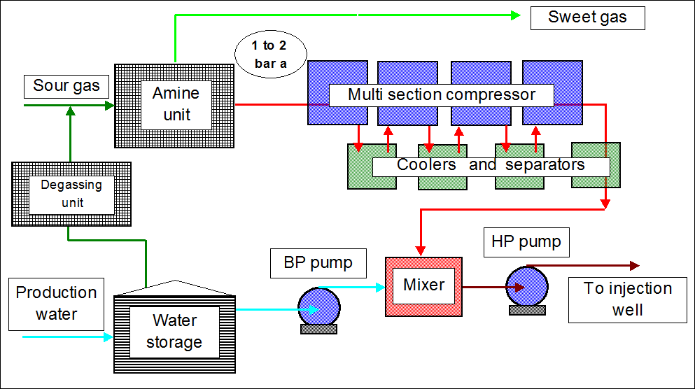
Conventionally, this operation is carried out using a pumping unit for the water, a compression unit for the acid gases and a mixer at the pumping and compression outlet. Compression of gases requires a lot of equipment, given the heating of gases during compression: in addition to rotating machines and their drive, heat exchangers as well as water-gas separators are required to avoid entrainment of water in the compression stage located downstream. See below a sketch of the installation.
When the mass flow rate of the acid gases is low, the gases can be completely dissolved into the water before reaching the re-injection pressure therefore saving a lot of compression energy. Downstream of the mixing point, the liquid mixture is raised in pressure using a monophasic pumping stage in order to reach the re-injection pressure. Concerning the equipment, when the volume flow rate of acid gases is low, compression takes place using positive displacement compressors. On the other hand, when it is high, the use of radial rotodynamic machines is preferable.
This equipment is particularly heavy and bulky. Furthermore, they require costly materials to take into account the aggressiveness of acid gases.
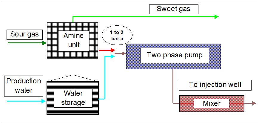
An alternative solution: a two-phase rotodynamic pump using helico axial hydraulic cells. Several arrangements may be considered:
Pressurization with two phase equipment
Basic arrangement: acid gases and water are mixed before their admission into a multiphase pump.
At this stage, a very small fraction of the acid gases is dissolved into the water due to the low inlet pressure (this pressure level depends on the gas treatment technology – Chemical versus physical dissolving agents). During compression, part of the acid gases gradually dissolve into water while the undissolved gases heat up in a compression mode intermediate between a polytropic (only gas) and an isothermal compression (continuous cooling at constant temperature). In the present situation, the temperature rise of the gases is moderate taking into account the constant cooling of the gases by water whose calorific capacity is higher than that of the gases. The cooling of the gas by water is facilitated by a very large contact surface (presence of numerous bubbles and pockets of gas as well as droplets of liquid) taking into account the permanent mixing of the two phases during compression. Of course, the cooling of the gas is accompanied by some heating of the liquid. See below a sketch of the installation.
Second arrangement: the two-phase gas – water mixture is extracted at an intermediate pumping stage
This is carried out in order to facilitate the dissolution of the gas phase into the water (reaching a dissolution equilibrium) in an external mixer before their introducion into the pump to finalize the two phase compression. At the end of compression, a last mixer may be used to reach the dissolution equilibrium condition. These external mixtures can be combined with cooling in order to enhance the dissolution and to facilitate the compression of the gas phase. Two comments must be made: a) It should be noted that dissolving a gas into a liquid is dependent on numerous parameters and takes some time even when the conditions for dissolution are met. This is called “Kinetics of dissolution”. b) cooling of CO2 and H2S must be made according to the dew point formation of hydrates.
Third arrangement: the two phase compression consists of two sections mounted back to back.
A first section comprises one or several large diameter radial impellers for the compression of a strictly gaseous phase allowing, at the same time, to substantially reduce the gaseous volume and to reach a significant dissolution fraction into the liquid phase. The liquid and gaseous phases are circulated into a mixer after this pre-compression stage before being introduced into a second two-phase pumping section composed of helico axial impellers. This back to back arrangement makes it possible to significantly reduce the input volume at the two-phase section and to raise both the pressure and the density of the two-phase mixture, two elements enhancing the “two-phase efficacy”.
See in the “Two-Phase” Chapter and the “Two Phase Pumps” section to see a) The definition of the “Two phase efficacy” (different to the Two Phase Efficiency) b) and how the two-phase efficacy varies with the GLR (Gas-Liquid Ratio) and the density ratio, GLDR.
http://yvcharron.com/index.php/two-phase-flow-pumps/
It should be noted that regarding these two-phase compressions, the two phase pump presents characteristics which are different from that corresponding to the pumping of a mixture of hydrocarbons.
For more details see the document below:

– In water-acid gas compression, the inlet volume flow rate (therefore the impeller geometry) is determined by the volume of the gas phase while the outlet volume flow rate (therefore the impeller geometry) is determined by that of the liquid phase which contributes to give a conical shape to the two-phase pump rotor unlike a pump dedicated to the pumping of two-phase hydrocarbons with little intermediate dissolution provides a cylindrical shape to the rotor.
– In water-acid gas compression, the compression of the mixture is rather ineffective at the inlet of the pump given the large volume of gas and the low density of the mixture while this compression is very effective at the outlet, the mixture consisting essentially of liquid with a very high density.
These two comments explain the advantage of dividing the multiphase pump into two sections mounted back to back (a single-phase gas section and a two-phase section) with a dissolution mixer in between these two sections.
This work was carried out in 2000 at IFP. For more information use form:
http://yvcharron.com/index.php/contact/ or