
CONTENT: 1_Introduction; 2_Gas turbine types; 3_Examples of gas turbine intermediate air process; 4_Description of an intermediate CO2 removal system; 5_System performance; 6_Carbon dioxide inventory; 7_Comparison between external and intermediate systems; 8_Conclusion; Annexe 1 – Combustion chamber pressure parameter; Annexe 2 – Artificial air dilution increase
1_Introduction
Carbon dioxide concentration into the atmosphere is a major issue. Unfortunately, this gas is not the only one responsible for atmosphere pollution. Other gases produced during fossil fuel combustion present similar danger like greenhouse effect, toxicity and acid rains. These gases are mainly water vapour, nitrogen oxides, carbon monoxide, hydrocarbons and fine particles. As such, all efforts to limit their emission should be undertaken. In this document, these gases are often included in the wording “Carbon dioxide” for simplification.
Page “Power plants – External CO2 removal” of this web site, describes how carbon dioxide produced in the combustion chamber of a gas turbine may be absorbed at a relatively high pressure and low temperature in a contactor by a physical solvent. This high pressure is achieved by a compression – expansion loop activated by the energy of the hot gas exiting the power turbine. This gas process is carried out externally to the gas turbine.
https://yvcharron.com/index.php/fossil-fuel-power-plants/
This mode of operation is transferrable to a steam boiler burning carbonated fuels (including coals) discharging to the atmosphere a polluted gas containing carbon dioxide at a relatively high temperature. The higher the exhaust temperature, the higher is the pressure level reached by the compression – expansion loop.
The present article presents a significantly different system where the carbon dioxide is capted upstream the combustion chamber. In that instance, the compression – expansion loop is operated from the turbine air compressor exit pressure level and not from the atmospheric pressure level. This gas process occurs internally (or more precisely at an intermediate position) to the gas turbine.
EXTERNAL and INTERMEDIATE treatments of the polluted air (mainly, carbon dioxide and NOx) present some similarities also relative advantages and disadvantages described below.
To determine the applicability of this intermediate air process, it is important to look at the characteristics of the different types of gas turbines (mainly aero derivative and heavy duty gas turbines) and other cases of internal air process.
More details concerning this presentation may be found in the PDF document below.

2_Gas turbine types
The mode of operation of gas turbines is presented in page “Power plants – External CO2 removal” https://yvcharron.com/index.php/fossil-fuel-power-plants/ and resumed below.
There are two main types of gas turbines: the aero derivative and the heavy duty (or industrial). They differ mainly by their application, their performance and their mode of construction.
As suggested by their name, aero derivative gas turbines are based on a central core engine derived from the aircraft industry (jet engine) discharging hot gases with a high momentum (in an aircraft, the backward engine thrust displaces forward the aircraft) towards a last turbine stage usually named Power turbine or Free turbine. These turbines operate with a relatively large thermal efficiency, of the order of 40%. As a result, less heat is rejected to the atmosphere due to an exhaust gas temperature usually lower than 500°C (an average of 450°C).
Industrial gas turbines differ from aeronautical design in that frames, bearings and blading are of heavier construction. Their thermal efficiency is smaller (30 to 35 %). As a result more heat is rejected to the atmosphere due to an exhaust gas temperature often larger than 500°C (an average of 550°C).
The relatively large compression pressure ratio of an aero derivative gas turbine (30 to 35) induces a relatively high temperature at the compressor exit (approaching 700 °C). In contrast, the lower pressure ratio of a heavy / industrial gas turbine (15 to 20) induces a lower temperature at the compressor exit (of the order of 500 °C°).
The temperature and the pressure levels at the GT compressor exit are two important parameters for the design of CO2 removal at an intermediate position in a gas turbine as it will be seen in this article.
More details concerning the different turbine types and some characteristics of an air compressor of a gas turbine may be found in the attached PDF (see above).
3_Examples of gas turbine intermediate air process
The normal air process in a gas turbine is as follows: ambient air is suctioned by a compressor, pushed towards a combustion chamber then released in an expander where the hot gas expansion provides sufficient energy to drive both the air compressor and an external load (an electric generator or a mechanical brake).
It is meant here by external and intermediate air process (or treatment for CO2 removal) the following:
- In an external treatment, the air flow circulates straight through the gas turbine with the gas treatment occurring after the gas turbine exhaust.
- In an intermediate treatment, the air flow exits the compressor, enters in a process unit then returns to the combustion chamber before being released by the power turbine. The gas treatment occurs inside the normal course of the gas turbine air flux.
More details concerning examples of gas turbine using an intermediate air process are described in the attached PDF: Gas turbines with air regeneration and also air compression with inter cooling (see above).
4_Description of an intermediate CO2 removal system
4.1_Stoichiometric combustion
Contrary to a reciprocating engine, the combustion in a gas turbine operates with an excess of air therefore of oxygen. This is required to prevent the temperature entering into the expansion section to reach a too high level and also to permit a sufficiently high mass flow rate across the gas turbine i.e. high power. In this mode of operation, it is said that the air entering the gas turbine is diluted.
In this document, we define the air dilution factor by the ratio of the number of oxygen molecules entering the gas turbine and those satisfying a stoichiometric condition. In the following, the air dilution factor is equal to 3.
4.2_Combusted air recycling with EXTERNAL air treatment
This mode of operation represents the case treated at page “Power plants – External CO2 removal” of this web site.
In this system, the hot burned gases are cooled down by a heat exchanger before being partially recycled in the gas turbine while the other part is directed towards the gas treatment system. As a reminder, this system includes a compression – expansion loop and a contactor operating at the highest pressure of that loop allowing dissolution of acid gas molecules (mostly carbon dioxide but also NOx) into a physical solvent. The gas recycling is required to provide the largest CO2 fraction into the gas turbine flux to ease its dissolution in the contactor. As a consequence, the gas turbine operates in a stoichiometric condition.
4.3_Combusted air recycling with INTERMEDIATE air treatment
Like in the previous paragraph, combusted air is recycled in order to provide a stoichiometric combustion in the gas turbine. However, in the present case, the air treatment occurs in between the air compressor exit and the combustion chamber inlet (see figure below). This permits to elevate the bottom (lowest) pressure of the compression – expansion loop (CpR – XpR) requiring a lower pressure rise in the CpR-XpR loop (compared to an external treatment) to reach a suitable pressure in the contactor.
This method presents however a significant disadvantage. Carbon dioxide molecules being generated in the combustion chamber, the fraction of the burnt gas which is not recycled is rejected into the atmosphere. As such, in the case of a dilution factor of 3, the fraction of CO2 rejected into the atmosphere is equal to 40 % of the carbon dioxide produced in the combustion chamber.
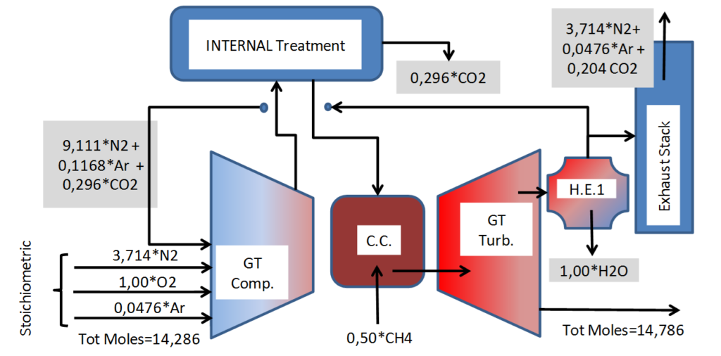
Intermediate treatment of compressed gases, gas turbine operating in stoichiometric condition. Air dilution provided by cooling and recycling burnt gases.
_
At the outlet of the gas turbine compression section the air flow exits the gas turbine casing (see figure below). It is successively cooled in heat exchanger HC1, compressed by CpR, cooled down again in HC2 to enhance sour gas dissolution before entering the contactor where liquid solvent is injected in extremely fine droplets (large liquid contact surface) to facilitate the absorption of the sour gas into the physical solvent. Downstream the contactor, the sweet gas is heated in heat exchanger HC3 before entering the expander XpR then heated again to recover all residual heat available from heat exchanger HC1. Heat exchanger HC3 receives the total heat available from HC2 and also a fraction of heat at high temperature from HC1 to get the maximum power delivered by expander XpR.
The maximum pressure level at the contactor is reached when the XpR delivered power equals to the CpR absorbed power representing the equilibrium status of the compression – expansion loop. A regulating system is required both to start the operation of the loop and to control the speed variation of the mechanically coupled machines (XpR and CpR – note that the mechanical link is not represented on figure).
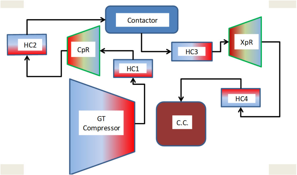
Intermediate treatment of compressed gases between GT compressor exit and combustion chamber inlet including compression CpR and expansion XpR sections, one contacting vessel and four heat exchangers HC1 to HC4 (In reality, two vessels)
More details concerning the description of an intermediate CO2 removal system may be found in the attached PDF (see above)
5_System performance
5.1_Fractions of sour gases absorbed and rejected to the atmosphere
The degree of air dilution is adjusted (or fuel mass flow rate) to provide an acceptable temperature at the exit of the combustion chamber preventing damages to the first stages (fixed vanes and rotating blades) of the high pressure turbine section.
A large fraction of air dilution corresponds to a large fraction of recycled burnt gas and therefore to a large fraction of capted sour gases, therefore, to a low fraction of rejected sour gases. To the contrary, when the air dilution factor is small, the fraction of recycle burnt gas is small and the fraction of rejected sour gases is relatively high. As an example, the absorbed (rejected) sour gas is 60 % (40 %) for an air dilution factor of 3. It is 72 % (28 %) for an air dilution factor of 4.
5.2_CpR compression, XpR expansion and heat exchangers duties
Calculation results presented on table below are based on one mole of di-oxygen per second that is 32 g/s or 411 g/s total inlet flow.
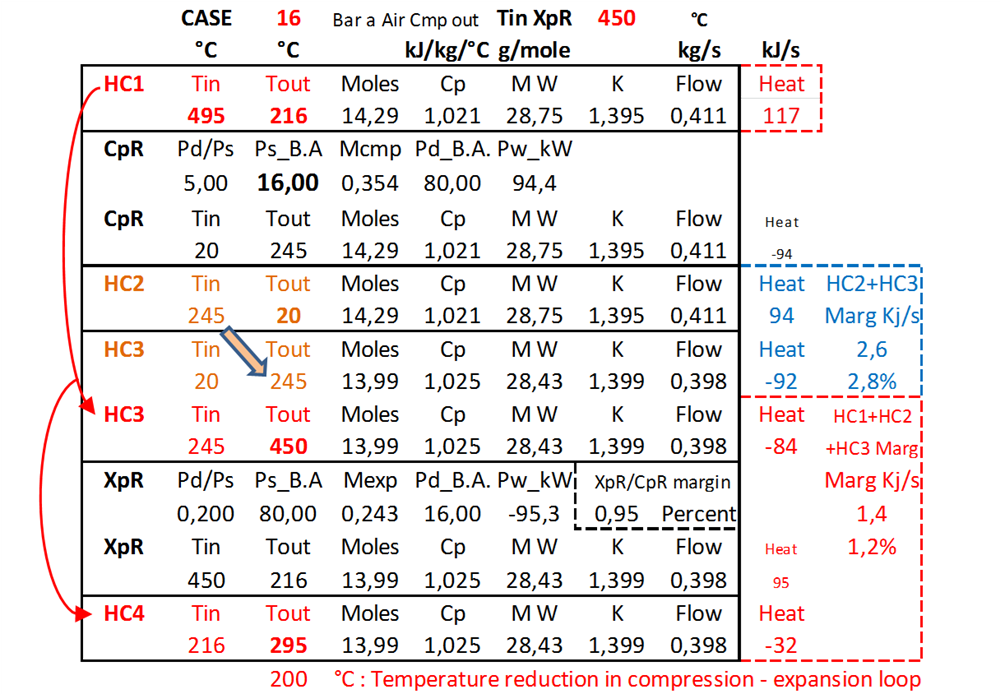
Example of CpR, XpR and heat exchangers operating data based on 496°C inlet temperature at the compression – expansion loop. Note: data correspond to one mole of oxygen at gas turbine entrance
_
Based on a 496°C air compressor exit temperature, the compression and expansion pressure ratio approximates, respectively, 5.0/1 and 1/5.0 at the equilibrium point corresponding to a contactor pressure of 80 Bar abs for an inlet pressure of 16 Bar abs. At this pressure level, acid molecules (carbon dioxide and NOx) are removed from the polluted gas in the contactor. The successive polytropic compression and expansion generates a reduction in the gas temperature of approximately 46 °C (from 496 to 450 °C).
5.3_CpR and XpR polytropic efficiencies
The compression – expansion loop performance has been evaluated for several values of polytropic efficiencies. In these calculations it is admitted that the expander efficiency is 5 points above the compressor efficiency, that is, when the compression efficiency is equal to 80 %, the expander efficiency is assumed equal to 85 % (basis of these calculations).
When the CpR efficiency reaches 84 % the pressure ratio is 7.2 and the contactor pressure is 115 Bar abs. When this efficiency is reduced to 76 %, these values become, respectively, 3.65 and 58.4 Bar abs.
5.4_Incidence of air compressor pressure ratio on contactor pressure
The compressor exit temperature varies considerably with the compressor pressure ratio, reaching, for example 600 °C for a pressure ratio of 23 and considerably higher values for greater pressure ratio. This increase in temperature provides a larger energy exchange in the compression – expansion loop permitting the loop to operate with an increased pressure ratio, therefore, the contactor operating at a higher pressure level.
Variation in the compression – expansion loop has been studied versus the XpR inlet temperature (i.e. main compressor pressure ratio). These calculations were performed assuming a temperature decrease in the compression – expansion loop of 46 °C (496 °C at main compressor exit, 450 °C at XpR inlet and also 450 °C at combustion chamber inlet). Considering a compressor pressure ratio of 19.75 corresponding to a XpR inlet temperature is 510 °C (air compressor exit 555 °C), the compression – expansion loop reaches a pressure of 130 Bar abs (contactor operating pressure) representing an increase of 0.77 bar per °C at the inlet of the XpR expansion.
5.5_Gas turbine overall performance
5.5.1- Gas turbine without CO2 removal – Conventional design
The overall performance of a gas turbine operating with a 16/1 main air compressor pressure ratio has been analysed based on one mole of di-oxygen (same for water vapour and half for methane and carbon dioxide). Based on stoichiometric condition and a dilution factor of 3, the temperature at the combustion chamber exit is 1428 °C. Based on a GT expansion efficiency of 80 %, the expansion power is 337 KW. For a conventional turbine (no CO2 removal), the thermal efficiency is 35.6 %.
5.5.2- Gas turbine with CO2 removal – Pressure and heat losses
To compensate for pressure losses in the compression – expansion loop, the pressure ratio of the main air compressor is increased from 16/1 to 19/1. This pressure increase represents either a 3 Bar pressure compensation at 16 Bar abs (18.75%) or a 15 Bar compensation at 80 Bar abs (also 18.75%). The increase in pressure ratio provides an increase in temperature of 48 °C at the compressor exit. This pressure rise is obtained by an increase in the GT compressor absorbed power (222 kW) reducing the thermal efficiency to 30.2 %.
To compensate for heat losses and temperature reduction in the compression – expansion loop (temperature at the combustion chamber inlet reduced from 496 to 295 °C) an additional 74 kW has to be supplied in the combustion chamber reducing the thermal efficiency to 25.3% (this takes into account the additional heat provided by the increase in pressure rise from 16/1 to 19/1).
5.5.3- Gas turbine with CO2 removal – Heat and energy recovery
Three types of heat and energy may be recovered. They include:
- Residual heat from heat exchanger HC1. 82 kW heat available from that source at 216 °C. A fraction of that heat could be supplied to a solvent boiler assuming that 1% of the fuel heat rate (454 kW) could be required for it that is 4.5 kW.
- Carbon dioxide pressurisation. Compressing CO2 from 1 Bar a (following recycling) to 80 Bar a represents a potential energy of 9 kW. Half of that energy could be recovered by depressurising the liquid solvent – sour gas mixture in a two phase flow turbine representing 4.5 kW.
- CpR – Xpr energy excess. In the present case (16 Bar abs), 1 kW may be recovered. This figure increases significantly with the combustion chamber pressure (see annexe A1).
Recovering the above 5.5 kW mechanical energy and adding them to the driving load (115 kW) the thermal efficiency is raised to 26.5 %.
Recovering the 4.5 kW heat energy (item a) raises the thermal efficiency to 27.5 % (8 points below the thermal efficiency of a conventional gas turbine). It will be seen in annexe A1 that when the air compressor pressure ratio increases, the difference between the two thermal efficiency values reduces.
5.6_Physical solvent regeneration
Following sour gas absorption by fine solvent droplets, these latest fall at the bottom of the contactor vessel where the solvent is extracted for depressurisation in a second vessel. The purified liquid at the bottom of the depressurisation vessel is pressurised in view of its reinjection at the top of the contactor vessel for a new cycle of sour gas removal.
The physical solvent may be depressurised, at least, in three different manners:
- Through a let-down valve – no energy recovery (constant enthalpy).
- Through a single phase flow turbine (radial hydraulic cells) providing little energy recovery. This equipment is relatively inefficient when the gas volume fraction becomes greater than the liquid volume fraction. The two phase flow efficacy is considerably reduced. See: https://yvcharron.com/index.php/two-phase-flow-pumps/ )
- Through a two phase flow turbine recovering most of the energy resulting from the gas expansion. This equipment, using helico axial hydraulic cells, is efficient for all gas volume fractions. Concerning the operation of a two phase flow turbines see: https://yvcharron.com/index.php/two-phase-flow-turbines/
The regeneration process of a physical solvent using two phase flow turbines is detailed in the present web site: https://yvcharron.com/index.php/gas-treatment/.
The energy provided by the depressurisation of the two-phase solvent liquid – sour gas (gas expansion) is greater than the energy required for the pressurisation of the purified liquid solvent (no compressibility).
More details concerning the system performance may be found in the attached PDF
6_Carbon dioxide inventory
In 2019, the total world emission of CO2 per year was 34 169 MTons according to Wikipedia: https://fr.wikipedia.org/wiki/%C3%89mission_de_dioxyde_de_carbone
In 2017, the total world electricity production was 25 000 TWh according to CEA Energy Handbook https://www.cea.fr/multimedia/Pages/editions/ouvrages/memento-sur-energie.aspx
In this study, it is assumed that CO2 emission is 4.0 MT/MW/year which may be considered a minimum compared to coal and liquid fuel values.
Limited to carbon fuels, world electricity production and CO2 emission per year were:
| SECTOR | Coal | Liquid fuel | Gas fuel | TOTAL |
| Energy TWh | 9 575 | 925 | 5 775 | 16 275 |
| CO2 emitted – GTons | 4.43 | 0.43 | 2.67 | 7.53 |
| CO2 emission relative to total emission in per cent | 12.97 | 1.25 | 7.82 | 22.0 |
In recent years, 7.5 GTons per year of CO2 were emitted by conventional thermal electrical equipment burning coal, liquid and gas fossil fuels that is 22 per cent of the total world CO2 emission.
Coal represents the largest emission (13 %) followed by natural gas (7.8 %) then liquid fuel (1.2 %).
Whatever boilers or gas turbines are considered and whatever External or Intermediate treatment systems are used, they offer the possibility to absorb a large fraction of the CO2 produced.
More details concerning the carbon inventory may be found in the attached PDF
7_Comparison of external and intermediate systems
Below is a comparison between the two systems with their relative advantages (blue) and disadvantages (red).
| INTERMEDIATE removal | EXTERNAL removal | |
| Cmp-Exp loop bottom pressure | Main air compressor exit pressure | Atmospheric pressure |
| Cmp-Exp loop top pressure | Depends on main air compressor pressure ratio | Depends on gas turbine thermal efficiency |
| Cmp-Exp loop complexity | Only one “CpR-XpR” stage – Little complexity | Three “CpR-XpR” stages – Large complexity |
| Comp-Exp loop common to several turbines | Not possible -Limited CpR-XpR efficiency due to small flow | Possible – Large CpR-XpR efficiency due large flow |
| Impact on existing installations | GT revamping – Impact on GT control system to be evaluated | No impact on GT package – Little impact on GT control system |
| Liquid solvent entrainment | No consequences – Burnt into combustion chamber | Rejection into atmosphere of finest droplets |
| Impact on GT perf. | Small degradation | Small degradation |
| CO2 and NOx removal | Partial – Approx. 60 % | Total – No atm. rejection |
The main advantage of CO2 removal at GT intermediate stage is the less complexity of the compression-expansion loop (high bottom pressure) requiring only one compression – expansion stage. It should be noted that for a given contactor pressure, the energy loss in the compression-expansion loop reduces when the main compressor pressure ratio increases (blue parameter) resulting at the same time by an increase in the air temperature (more energy available).
The main disadvantage of this arrangement is the significant rejection of CO2 in the atmosphere. The amount of CO2 rejected into the atmosphere reduces when the GT inlet air dilution increases. This arrangement requires also a modification of the gas turbine internals (between air compressor and combustion chamber).
The main advantage of a CO2 removal after GT exhaust is the total removal of CO2.
The main disadvantage of this arrangement is a larger complexity of the compression-expansion loop (bottom pressure is atmospheric) requiring a large number (usually three) of compression and expansion stages. The compression requirement reduces when the exhaust temperature increases (green parameters on table below).
In both cases, the compression – expansion loop operates better when the CpR and XpR efficiencies are high. This is obtained mostly when the flow rate is large (red parameters on table below).
| Supplied power MW | Thermal efficiency per cent | Air comp. Pressure ratio | Mass flow kg/s | Vol flow km3/hr | Exhaust temper. °C (1) | Heat rate kJ/kWh | |
| T21 | 10.4 | 34.8 | 16.0 | 33.8 | 94 | 508 | 10 342 |
| T22 | 24.5 | 33.6 | 14.0 | 81.3 | 225 | 543 | 10 720 |
| T23 | 39.8 | 40.3 | 24.3 | 115 | 318 | 468 | 8 922 |
| T24 | 50.0 | 39.4 | 19.8 | 125 | 346 | 560 | 9 147 |
| T25 | 187 | 36.5 | 12.8 | 558 | 1 545 | 536 | 9 863 |
| T26 | 329 | 41.0 | 20.1 | 724 | 2 004 | 599 | 8 780 |
| T27 | 593 | 42.8 | 24.1 | 1050 | 2 907 | 670 | 8 411 |
More details concerning this presentation may be found in the PDF document below.
8_Conclusion
Intermediate and external CO2 removal systems based on a physical solvent require a compression – expansion loop to rise the pressure of burnt gases and to permit the solvent contactor to operate at a relatively high pressure.
Complexity of the compression – expansion loop (CEL) – CO2 removal in a GT intermediate system requires a relatively simple arrangement of the CEL (high bottom pressure). This complexity reduces as the pressure at the main air compressor exit increases requiring less pressure rise in the CEL and causing less energy losses. To the contrary, CO2 removal at GT exhaust requires a relatively complex arrangement (atmospheric bottom pressure): three sections of compression and expansion. In both cases, a high expansion temperature (CEL) facilitates the pressure rise.
Fraction of CO2 removal – CO2 removal in a GT intermediate system is limited to 60 % (complement rejected to atmosphere) for a GT air dilution factor of three. This percentage increases with the air dilution factor. To the contrary, CO2 removal at GT exhaust is total.
Efficiency of the CEL – Polytropic efficiency of the CEL is dependent mostly on the volume flow of the gas to be treated. The highest this parameter, the highest the Reynolds number, the lowest the friction losses and the highest the compression and expansion efficiencies.
Thermal efficiency of the overall system – This efficiency is mostly dependant on the gap between the combustion chamber pressure and the contactor pressure. The losses in the CEL loop are of three types: pressure and heat losses and residual heat in one heat exchanger. Energy may be recovered in three directions: residual heat transferred to the solvent boiler (if any), depressurisation of the liquid solvent – sour gas mixture and energy excess in the CEL loop. As an overall, the GT thermal efficiency is relatively unchanged when the air compressor pressure ratio is high.
Gas turbines elected to CO2 removal in a CEL using a physical solvent – Two cases may be considered. Case a) Gas turbines presenting a relatively large GT air compressor pressure ratio (therefore exit temperature) facilitating CO2 removal at intermediate position. The higher this parameter; the lower is the impact on the GT thermal efficiency. It should be preferably greater than 16/1. Case b) Gas turbines presenting a relatively large exhaust temperature (low GT thermal efficiency) facilitating CO2 removal at GT exhaust. It should be preferably above 550 °C.
Combined CO2 removal in a multi turbine power plant – Combined CO2 removal based on an intermediate extraction system is not possible for several gas turbines due to the lack of individual GT control (combustion chamber temperature, running speed, flow ratio). To the contrary, combined CO2 removal based on an exhaust system is possible for several gas turbines (and boilers) as the turbine control systems are not active at this location. It should be added that the larger the flow rate, the larger is the efficiency of the CEL.
Physical solvent regeneration – Energy may be recovered during the two phase expansion of the solvent liquid – sour gas mixture by using a two-phase flow turbine (helico-axial design). It is greater than the energy required to pressurise the purified solvent.
Carbon dioxide emission – In 2019, total world emission of CO2 per year was of the order of 34 GTons. Electrical generation using carbon fuels (coal, liquid and gas fuels activating boilers and gas turbines) would contribute to 22 % of that emission. Most of these electrical generation emissions could be capted in contactors using physical solvents.
_
Annexe 1 – Combustion chamber pressure parameter
This annexe has been added in April 2021.
In section 5.2, the system performance has been analysed in the worst case of air compressor pressure ratio (16/1) corresponding to a pressure of 16 Bar abs (a relatively low pressure) at the combustion chamber. In this annexe, an analysis is performed based on a wider range of combustion chamber pressure (16 to 32 Bar abs) keeping constant the contactor pressure.
In this annexe, calculations have been performed on the following basis:
- The contactor pressure is constant and equal to 80 Bar abs.
- One mole of di-oxygen per second (32 g/s).
- Pressure losses in the compression – expansion loop are assumed proportional to the pressure difference between the contactor pressure and the air compressor exit pressure.
- Temperature reduction (due to heat losses) in the compression – expansion loop is equal to 30 °C.
- The temperature at the expander (XpR) inlet is equal to 450 °C.
As shown in section 5.5.2, when the combustion chamber pressure is equal to 16 Bar abs the thermal efficiency is reduced from 35.6 % (No CO2 removal) to 25.3 % (10 points less). When that pressure is equal to 32 Bar, the thermal efficiency is only reduced from 39.6 % to 32.7 % (7 points less). These calculations do not take into account energy recovery.
Three types of energy may be recovered: a) Residual heat from heat exchanger HC1; b) Carbon dioxide pressurisation; c) Energy excess in CpR – XpR loop.
When the combustion chamber pressure is equal to 16 Bar abs, the thermal efficiency is increased from 25.3 % to 26.5 % by considering energy recovery provided by carbon dioxide pressurisation and CpR – XpR loop. It would be increased to 27.5 % by supplying a relatively small fraction of residual heat from heat exchanger HC1 to the solvent boiler. This last figure is approximately 8 points below the “No CO2 removal” thermal efficiency.
When the combustion chamber pressure is equal to 32 Bar abs the thermal efficiency is increased from 32.7 % to 36.3 % by integrating the two above mechanical energies. It is then increased to 37.3 % by integrating heat recovery from heat exchanger HC1. This last figure exceeds by 2 points the “No CO2 removal” thermal efficiency.
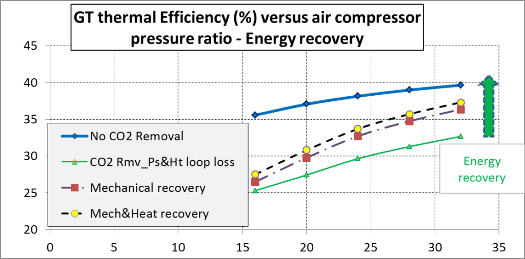
Gas turbine thermal efficiency versus air compressor pressure ratio for three cases: a) No CO2 removal; b) CO2 removal integrating pressure and heat losses in CpR – XpR loop; c) Mechanical energy recovery; d) Mechanical and heat energy recovery.
_
Annexe 2 – Artificial GT inlet air dilution increase
This annexe has been added in April 2021.
Adding a fraction of oxygen to the atmospheric air flow reduces the relative fraction of nitrogen at the gas turbine inlet. This reduction in nitrogen molecules is compensated by an increase in carbon dioxide molecules (increased flow recycling). This permits to increase the fraction of carbon dioxide flowing through the compression – expansion loop and, therefore, the degree of absorption of that gas.
In that situation, less carbon dioxide is emitted into the atmosphere.

Keywords: Power plant carbon dioxide NOx CO2-removal compression expansion loop emission inventory.