
Keywords: Fossil fuel engines energy recovery Rankine cycle carbon dioxide CO2 captation physical solvent pressurised pneumatic reservoir
Introduction
Previous sections focussed on large fossil fuel power plants. In these land based installations, it is possible to deploy large and sophisticated means of energy recovery (heating of residential buildings, vapour generation also use of Rankine or combined cycles) as well as carbon dioxide captation (involving chemical or physical solvents), processing and storage of toxic gases produced during fuel combustion. Downstream of these facilities, toxic gases, particularly, carbon dioxide can be injected into a pipeline or into the ground.
For mobile energy production units (road or maritime), energy recovery and sour gas treatment conditions are considerably less easy requiring means adapted to the situation.
In this twenty first century, the environment pollution is such that electrical vehicles are foreseen as the main solution for resolving some of the environment damages. However, this does not take into account all the new constraints which are going to be generated in a world centred on electrical energy. To the contrary, the future may progressively organize a mix of energy for vehicles including electricity, fuel cells, hydrogen, powered air and fossil fuel. Electrical batteries are not at all adapted to large engines (trucks, trains, boats) for which, combustibles like hydrogen, natural gas and LPG may be more adapted to the situation. To severely reduce the CO2 concentration into the environment, the use of fossil fuel may only be permitted if fuel engines increase significantly their thermal efficiency and are designed to capture the CO2 produced at its source of emission and to store it until a delivery point.
Exhaust heat recovery system – Wikipedia – Even if current engines consume less fuel than they used to, the thermal efficiency of an internal combustion engine has not really increased since its creation. The peak efficiency reached by a 4-cycle Otto cycle engine is around 35%, which means that 65% of the energy contained in the fuel is lost as heat. High speed Diesel cycle engines fare better with around 45% peak efficiency, but are still far from their Carnot efficiency, and hence 55% of the fuel energy content is lost.
https://en.wikipedia.org/wiki/Exhaust_heat_recovery_system
Research in Vehicles With Thermal Energy Recovery Systems – 19th International Conference on Knowledge Based and Intelligent Information and Engineering Systems – Andrew Royale and Milan Simic: On average, exhaust gas temperatures can range from 500 – 900 degrees, which is dependent on different automotive manufacturers and design requirements – https://pdf.sciencedirectassets.com/
Carbon dioxide capture from internal combustion engine exhaust using temperature swing adsorption – Shivom Sharma and François Maréchal – The temperature of engine exhaust normally range from 350 to 700°C – https://www.frontiersin.org/articles/10.3389/fenrg.2019.00143/full
ENERGY RECOVERY
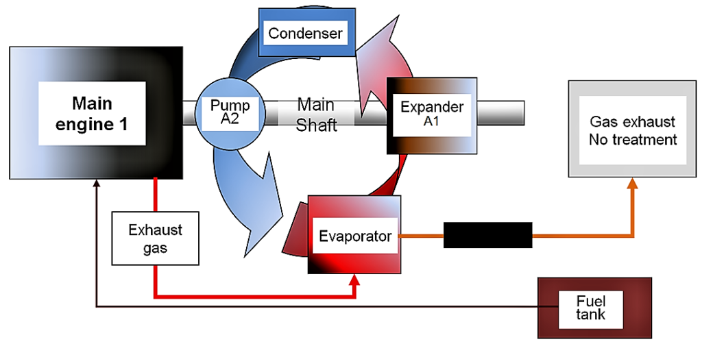
For most fuel engines (reciprocating or gas turbines), a significant part of the heat generated during the combustion is released into the atmosphere. As described in a few documents, this heat could be recovered in an auxiliary thermal cycle (Rankine or equivalent – See figure below) producing mechanical energy and helping to reduce the power supplied by the main engine. In the case of a reciprocating engine, the temperature of the burnt gases is very high because the air dilution of the gas is low (stoichiometric combustion). On the other hand, in the case of a gas turbine, the temperature of the fumes is lower but the dilution rate greater. If one gains in theoretical efficiency (Carnot efficiency – ratio of hot and cold absolute temperatures) in the first case, the quantity of combustion air is more important (therefore the energy) in the second case. It is difficult at this stage to determine which machine can provide the best overall performance within considering its exact characteristics.
ENERGY STORAGE OPTIONS
The energy storage could be done in different ways: electric, kinetic, pneumatic (storage of air or burnt gases at high pressure – A potential energy) or other means. If electricity was selected it could be combined with photovoltaic cells. The pneumatic system may provide several advantages; in particular, it allows the captation of the toxic gases resulting from the combustion usually released into the atmosphere. This may be carried through a compression / expansion cycle involving the burnt gases.
CYCLE OF A PNEUMATIC SYSTEM ACTIVATED BY COMBUSTION GASES
After passing through the evaporator of a Rankine cycle, combustion gases are cooled down before and after a pressurisation process B1 (First cycle sequence). The cooling process consists in transferring the heat to either a thermal cycle in view of producing energy or to an expander B2 (Last cycle sequence) for increasing the delivered energy. Gas cooling before pressurisation permits to reduce the compression energy while gas cooling after pressurisation permits to increase the solubility of the sour gases into a solvent (Tank A – Intermediate cycle sequence). Combustion gases are pressurised to around 700 bars (pressure usually considered for hydrogen storage – tanks made of composite materials). In the storage tank A, during and following the compression process, the burnt gases are brought into contact with a physical solvent distributed into droplets with an extremely small diameter for increasing the surface exchange (Circuit 1 – MeOH captation).
_
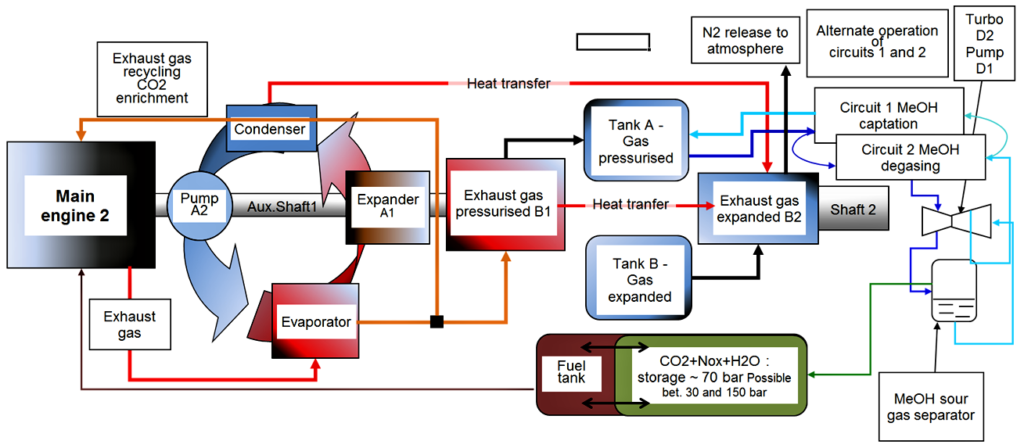
The liquid solvent requires later on to be processed for its regeneration. In the simplest situation, the solvent (for instance, methanol) may be discharged from its maximum operating pressure (for instance, 700 bars) at a service station, for instance, during a refuelling process. Another solution is presented in the attached document (Solvent management and purification – See above figure).
More details may be found in the following PDF document:

Carbon dioxide capture from internal combustion engine exhaust using temperature swing adsorption – Shivom Sharma and François Maréchal –
https://www.frontiersin.org/articles/10.3389/fenrg.2019.00143/full
Carbon capture and storage from automobile exhaust to reduce CO2 emission – Muthiya, Amarnath, Senthil Kumar and Mohan Kumar –
http://www.ijirset.com/upload/2014/special/tapsa/7_TAPSAAUTO001.pdf
CONCLUSION
The overall system includes a large number of equipment significantly increasing the mass of the vehicle. On the other hand, it helps to considerably reduce the size of the main fuel engine and also the fuel consumption therefore the fuel tank (optimized main engine operation, use of a Rankine cycle, removal of some heat from the condenser for the benefit of the combustion gas expander) but, above all, it allows most of the CO2 usually emitted to the atmosphere to be captured at the source of emission in the case of road vehicles, trains and boats, the largest CO2 emission contributors on the planet. This system could be envisaged initially on the largest equipment that can gradually lead to a miniaturization of the system.
This work was carried out in 2007. For more information use form:
http://yvcharron.com/index.php/contact/ or