
With the present design, the pylon supporting a three-blade wind turbine obstructs the wind passage causing aerodynamic and mechanical issues. These issues are all the more important as the diameter, the height of the pylon as well as the wind velocity are important. This section describes a system providing an attenuation of the dynamic excitations induced by the wind during the crossing of the pylon supporting the rotor of a wind turbine as well as the excitations caused by the passage of a blade in front of the pylon in the wind direction.
Aerodynamic excitations
These excitations may present different characteristics according to the flow conditions and dynamic. In the first case (No blade passing – pylon only), the excitations are substantially stationary insofar as the wind is itself stationary (constant intensity and direction). In the second case, it is the passage of the blade in front of the pylon which disturbs these excitations transferring them in a certain way from downstream to upstream then from upstream to downstream, that is to say from the pylon to the blade and vice versa. These latter excitations present, therefore, a non-stationary character.
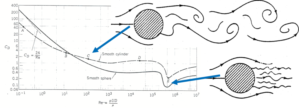
Flow drag of a sphere and of a cylinder versus the Reynolds number. The disturbances behind the obstacles are dependant on the Reynolds number. At low – medium Reynolds number cyclic shedding are formed behind the obstacles. At high Reynolds number there is a decrease in the regularity of the vortex structure with a flow fully turbulent behind the obstacle
_
More information’s may be found in:
Concerning the Reynolds number: https://en.wikipedia.org/wiki/Reynolds_number_
Flow drag on sphere and cylinders for several Reynolds number and with photographs on streamlines: http://brennen.caltech.edu/fluidbook/externalflows/drag/dragonasphere.pdf
_
The almost stationary excitations induced on the pylon resemble Karman vortices flowing downstream of the pylon and fading away behind it. These excitations have a slightly non-stationary character when we look at the individual evolution of a Karman vortex (characterized by a succession of lateral cyclic displacements). The emergence of large turbulences downstream of the pylon increases the apparent diameter (and cross section considering the pylon height) of the pylon (hydraulic diameter) representing the lateral width (and section) where the air does not flow naturally (curved streamlines).
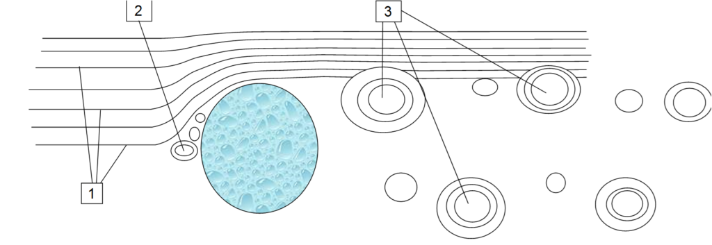
Representation of an air flow around a pylon, with circular shape, of a conventional wind turbine. The wind displaces the air from the left of the pylon (symbolised by longitudinal and parallel streamlines) to the right side where Karman vortices take place. This figure is representative of a non passing blade situation (pylon alone). The flow around the pylon may be called “stationary”.
_
Concerning the second type of excitations, when a blade passes in front of a pylon section and more precisely in front of the “hydraulic” section of the pylon, the force exerted by the air on the blade is considerably reduced, the air being not able to flow naturally downstream of the blade. When passing in front of the pylon, the blade is discharged from the driving force (transmitted to the rotor) and then suddenly recharged by leaving the hydraulic section of the pylon. These load changes cause dynamic bending to the blade resulting in mechanical fatigue which occurs at the frequency of passage in front of the pylon for an individual blade and at a triple frequency for the pylon of a tri-blade arrangement.
One solution to reduce these excitations would consist in installing a profiled mobile body mounted on the periphery of the pylon.
_
Adding a profiled body around the wind turbine pylon
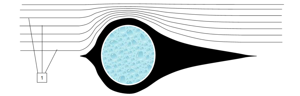
Representation of an air flow around a profiled body surrounding a pylon with a circular shape. The wind displaces the air from the left of the pylon (symbolised by longitudinal streamlines) to the right side where Karman vortices have been considerably reduced. This figure is representative of a non passing blade situation (pylon alone).
_
The mobile body includes, upstream, a cylindrical part surrounding the pylon over a large height but with a small thickness because it does not undergo significant mechanical stresses and, downstream, of a flat-shaped drift (flat plate) lying in the vertical direction and passing through the axis of the pylon. The cylindrical part and the flat plate are connected by concave shapes aimed at facilitating the guiding of the flow around the pylon and at reducing the mechanical forces between the cylindrical and planar parts. This results in a strong attenuation of the Karman vortices limited in their lateral displacement and, consequently, a significant decrease in the hydraulic diameter of the pylon (and in the hydraulic cross section).
_
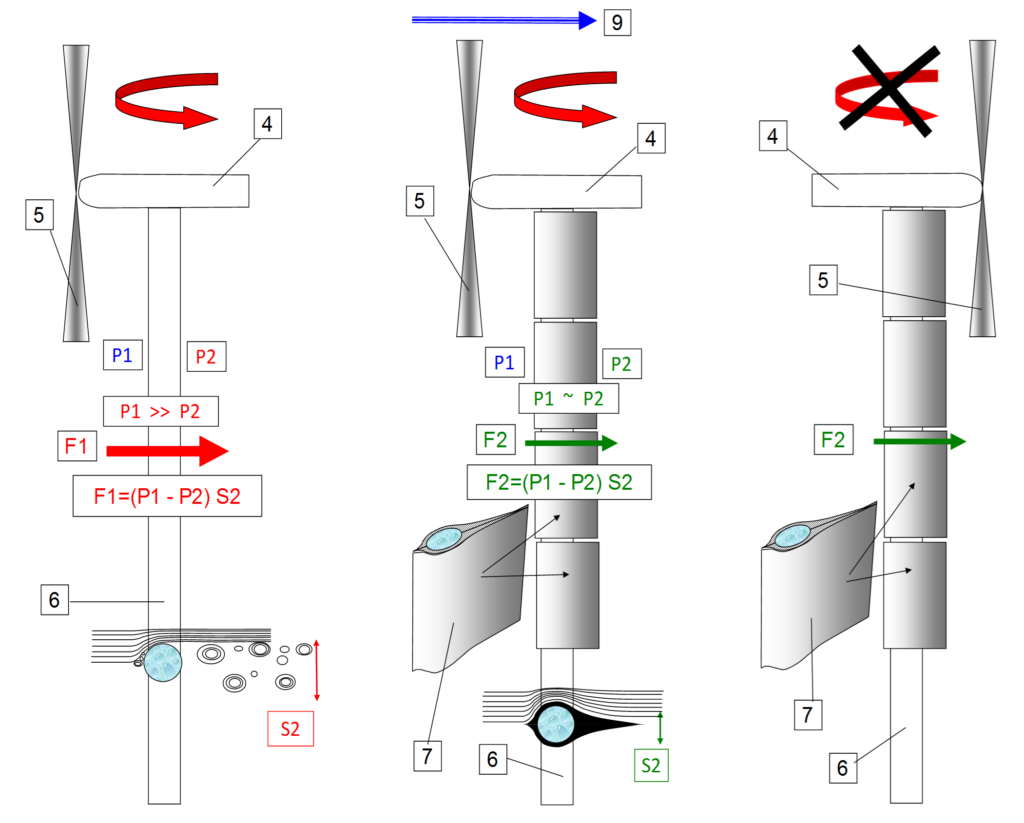
Figures on the left describe three situations:
a) Left – Conventional pylon (6) i.e. not including a profiled body. The resisting force F1 is large considering the large pressure differential (P2-P1) and the large hydraulic diameter (S2) of the pylon (with Karman vortices behind it).
b) Middle – Pylon including a profiled body or several (7), the resisting force F2 is minimized considering the structuration of the flow behind the pylon (reduced Karman vortices, hydraulic diameter and pressure differential)
c) Right – Profiled body system connected to the nacelle (4) preventing the rotor and blades (5) to pass behind the wind (9) and also to facilitate the gyration of the rotor (rotor mechanically driven by the profiled body).
_
The profiled body is designed to rotate freely (use of ball bearings or equivalent) around the pylon according to the wind direction. Due to its profile shape and its mounting mode around the pylon, the mobile body is automatically oriented facing the wind (profiled body tail behind the pylon) similarly to the blades. The only difference is that the blade rotor of a wind turbine is driven mechanically by the control system (energy required to position the rotor to face the wind).
A multi profiled body system may be used to facilitate the mounting and dismounting of an individual profiled body and to carry out their maintenance. The overall length covered by the profiled body is approximately equal to the blade length. Near the rotor centre, the requirement is less.
When passing in front of the pylon, the dynamic forces on the blades are reduced taking into account a reduction in the hydraulic cross section of the pylon by the use of a profiled body. It should be noted that the excitation frequency is three times the frequency of rotation of the rotor for a three blade system (conventional wind turbine).
Another consequence is a noise reduction. The noise increasing with the amplitude of the air waves which are dependent on the amplitude of both mechanical excitations and vortices, when these latest are reduced by using a profiled body (or several bodies) acting as an excitation dampener, the amplitude of the air waves is reduced.
In addition to its function of reducing the cyclic forces on the blades and the pylon, the profiled body can be used to facilitate the gyration of the rotor. This is represented in case c) of the above figure. It should be noted that with conventional wind turbines the bladed-rotor is controlled by positioning it upstream of the pylon (facing the wind). This is necessary to prevent the rotor to pass behind the pylon (blades not facing the wind).
In the case of the guidance of the blade – rotor by the profiled movable body, a mechanical system may be used to connect the profiled body to the nacelle or to the axis of the rotor so as to permanently orient the rotor towards the wind direction. The guiding force provided by the profiled body is proportional to the planar section of the profiled body multiplied by the sinus of the angle made by the direction of the wind and the position of the profiled body. To take two examples: a) when the blade – rotor and the profiled body both face exactly the wind direction, no correction is required and the correcting force exerted by the profiled body is nil; b) when the blade – rotor face the wind direction with an angle ALPHA, the profiled body makes an angle of Minus ALPHA generating a force tending to reduce angle ALPHA.
Conclusion
There are several benefits in using a mobile profiled body around the pylon of a wind turbine:
In the case of a no passing blade situation (rotor stopped or between blade passages) and with a strong wind, the steady bending forces are reduced. In the case of a strong and unsteady wind, the fatigue of the pylon is reduced.
In the case of a passing blade situation (blade passing in front of the pylon) the blade – pylon interaction is reduced, limiting the mechanical fatigue of the overall system (blade bending, gearbox, electric generator, nacelle).
The wind turbine emitted noise with the characteristical frequency of three times the rotor frequency is reduced according to the mechanical and sound wave dampening.
A multi profiled body system may be used for maintenance purposes.
The profiled body system may be mechanically linked to the rotor nacelle to mechanically drive the rotor to the required position and to reduce or even suppress the energy required by an electric motor positioning the rotor towards the wind direction.
Keywords: wind turbine pylon blade aerodynamic interaction Karman vortices
Leave a Reply