Keywords: pipeline pump interaction multiphase flow boosting severe slugging control topside subsea
Multiphase pipeline case
A 20’’ liquid pipeline connecting the “Z” complex (Well head platform) to the “P” production platform has been converted to the transport of multiphase flow. Operated by the natural field pressure and due to the increase in pressure drop when transporting multiphase flow, the pipeline pressure outlet is not sufficient to export the gas from the production platform (inlet pressure too low for the export compressors) requiring pressure boosting along the pipeline.
As gas flaring could not be envisaged, the use of multiphase flow pumps has been investigated. Three pump location cases have been analysed: At the “Z” platform with, unfortunately, limited power supply and two locations at the “P” platforms. These two locations are the platform topside (top of the “P” inlet riser) and the seabed (bottom of the “P” inlet riser).
_
Adding a multiphase flow pump
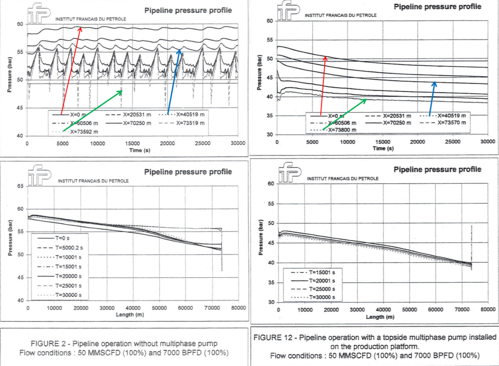
Multiphase flow analysis has been carried out for several stationary modes of operation, without and with the use of a multiphase pump, to illustrate how this equipment can help in suppressing severe slugging and in reducing the level of injection pressure at the pipeline inlet. Very little difference has been observed between the two cases of pump installation at the “P” platform: pump mounted immediately upstream (sub-sea) and downstream the riser (topside).
Analysis has also been carried out for some cases of non-stationary modes of operation (typically, shut-down and start up). They have shown the need for providing the pump with a minimum flow line and a check valve at the pump discharge. This analysis has permitted to quantify the response time of the pipeline and provided some indications concerning the operation of the pump (shut-down or start up sequence and timing). They have also shown an increase in absorbed power during the non-stationary modes of operation compared to the nominal flow case.
This study recommends the use and installation of a multiphase flow pump on the “P” platform.
SOME REFERENCES: Modeling of stratified two phase flow in pipes, pumps and other devices –
https://www.sciencedirect.com/science/article/abs/pii/0301932286900108
Modelling and simulation of transient air-water two phase flow in hydraulic pipes –
https://tel.archives-ouvertes.fr/tel-01651078v2/document
A study of terrain induced slugging in two phase flow pipelines –
https://www.sciencedirect.com/science/article/abs/pii/030193229400081T
For more details concerning the present simulation study –

In the case of a pressure at the “P” platform of 715 psia (49.3 bar abs), a multiphase pump, permits to reduce the inlet pipeline pressure from: a) 855 to 667 psia (59 to 46 bar abs) in the 100 % flow case (50 MMSCFD & 7000 BFPD); b) 841 to 551 psia (58 to 38 bar abs) when the gas flow rate is reduced by 60% and c) 979 to 841 psia (67.5 to 58 bar abs) when the liquid flow rate is increased by 200%.
Taking into account all the non-stationary modes of operation (start up, shutdown and change in production parameters), it is recommended to install a minimum flow valve and a check valve at the pump discharge. For these reasons, it is preferable to consider the installation of the multiphase pump on the “P” platform rather than on the sea floor.
In the case of a programmed shut-down of the pipeline, it is preferable to shut-down the multiphase pump before reducing the flow production.
To limit the pressure at the pipeline inlet and the maximum absorbed power during the pump start up, it is preferable to start the pump before the pressurisation of the pipeline.
The simulations carried out have demonstrated that: a) The production scenarios (start-up, shut-downs, etc) can be studied with existing simulation tools ahead of actual production start-up; b) An optimisation of the multiphase production system can be achieved by adjusting the various parameters (flow production, pump speed, pipeline equilibrium pressure); c) The simulation tools can also be used to train operators by demonstrating the process implication of certain actions.
These calculations were performed in 1999 with Two Phase pump hydraulics of the first generation (Poseidon technology). Should the calculation has been carried out with hydraulics of the second generation, less hydraulic stages would have been required (greater pressure coefficient and greater corresponding two phase efficacy) demanding less power from the driving machine (greater efficiency and greater corresponding two phase efficacy) –
http://yvcharron.com/index.php/two-phase-flow-pumps/