
keywords: carbon dioxide CO2 compression losses sonic choke surging liquid hydrate formation operability range two-phase flow
INTRODUCTION
Compression of carbon dioxide may present some difficulties in various areas. Carbon dioxide does not behave as an ideal gas; therefore, good knowledge of its thermodynamic properties is required. Attention should be paid to the relative gas velocity at the blade edges to avoid sonic losses and inside hydraulic cell channels to limit choke losses. Attention is required at low temperature to avoid the formation of carbonate hydrates and not to cool the gas at a too low temperature to avoid liquid formation especially during the compression of the fluid in a single phase condition. Above the critical point, the fluid behaves in terms of compressibility in between a gas and a liquid phase; therefore, hydraulic cells with adapted internal geometry are required to get an optimum pressure coefficient. Operability of a compression train may be of concern in terms of flow and running speed range around the design point. Special materials are required to take into account the aggressiveness of wet carbon dioxide (sour gas), the presence of hydrogen sulphide and also the occurrence of very low temperature following a sudden depressurisation of the compression facilities.
The benefit of a two phase compression system is sometimes questioned. This document investigates on the relative advantage of this mode of compression.
.
COMPRESSION SYSTEM ISSUES
1 – Single phase flow – Sonic losses
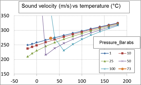
The speed of sound is the distance travelled per unit time by a sound wave as it propagates through an elastic medium. Its value depends strongly on the temperature as well as the medium through which the sound wave propagates. At 20 C, the speed of sound in air is about 343 metres per second.
In fluid dynamics, the speed of sound in a fluid medium (gas or liquid) is used as a relative measure for the speed of an object moving through the medium. The ratio of the speed of an object to the speed of sound in the fluid is called the object’s Mach Number. Objects moving at speeds greater than Mach1 are said to be traveling at supersonic speeds.
Concerning rotodynamic compressors, internals have to be designed according to the local relative gas velocity to limit losses occurring when this gas velocity approaches the speed of sound. These losses are designated by sonic losses.
The sound velocity reduces considerably with the temperature. In the case of carbon dioxide, at 25 bar abs, it is 200 m/s at minus 20 °C and 320 m/s at 170 °C. The sound velocity varies to the opposite of the pressure with a variation particularly important at low temperature but relatively small at high temperature. The sound velocity is approximately equal to 270 m/s at the critical point. At 50 bar, the sound velocity is increased approximately from 210 m/s at 20 °C to 245 m/s at 50 °C.
Attention must therefore be paid when operating a compressor with carbon dioxide at low temperature and medium pressure. For further details see attached PDF (See before “Conclusion” section) and also:
https://en.wikipedia.org/wiki/Speed_of_sound
2 – Single phase flow – Choke losses
Choked flow is a compressible flow effect. When it occurs, the fluid velocity (the flow rate) is considerably limited. It is associated with the venturi effect , that is, when a fluid flows through a constriction (such as the throat of a convergent – divergent nozzle) the fluid velocity increases causing the static pressure to decrease. Choked flow is a limiting condition where the mass flow will not increase with a further decrease in the downstream pressure for a fixed upstream pressure and temperature.
For homogeneous fluids, the physical point at which the choking occurs, for adiabatic conditions, is when the exit plane velocity is at sonic condition; i.e., at a Mach number of 1. At choked flow, the mass flow rate can only be increased by increasing the density (or the pressure) upstream the choke point
The critical pressure ratio is established according to the isentropic factor. In the case of nitrogen the critical pressure is equal to 0.528 the upstream total (stagnation) pressure. The choke flow rate is a function of the restriction characteristics: the upstream total pressure and temperature, the molecular weight and the isentropic factor. The lower are the pressure and the temperature, the lower is the critical mass flow rate.
For further details see the attached PDF and: https://en.wikipedia.org/wiki/Choked_flow
In the case of a rotodynamic compressor (axial or centrifugal), the chocked flow limit may be designated by overload.
3 – Two phase flow – Sonic characteristics
Several numerical expressions are available to calculate the sound velocity for a two phase mixture. Nguyen has proposed a model where the gas phase is homogenously dispersed in the liquid phase. This model has been used to analyse the characteristics of the sound velocity according to the gas – liquid mixture characteristics.
When the gas volume fraction tends, respectively, towards 1 and 0, the two phase sound velocity tends, respectively, towards the gas and the liquid sound velocity. In between, the sound velocity is reduced being smaller than the lowest (the gas) sound velocity.
At a low pressure (low gas volumetric mass), the two phase sound velocity may reduce to 20 m/s (that is 10 times smaller than the gas sound velocity). At medium pressure (of the order of 50 bar) the sound velocity is increased to 100 m/s. The two phase sound velocity approaches the gas sound velocity for a pressure greater than 150 bar.
For further details see the attached PDF (Before “Conclusion” section) with graph showing the characteristics of the sound velocity of a carbon dioxide gas – liquid mixture. See also: https://pastel.archives-ouvertes.fr/pastel-00005234/document
4 – Hydrates
Carbon dioxide hydrate or carbon dioxide clathrate is a snow-like crystalline substance composed of water ice and carbon dioxide. It is normally a Type I gas clathrate. In the case of pure carbon dioxide and at low pressure, clathrate formation occurs below 283K (10 C). See https://en.wikipedia.org/wiki/Carbon_dioxide_clathrate.
The temperature threshold (temperature at which hydrate formation occurs) increases slightly with the pressure: 10°C at 50 bar abs and 12°C at 150 bar abs.
The temperature threshold increases with the fraction of associated components: 13°C at 50 bar abs and 16°C at 250 bar abs in the case of a mixture containing 5 per cent of methane.
5 – Flow surging
Several cases of flow surging are considered in the present document.
5.a – Rotating stall is a local disruption of airflow permitting the compressor to continue to provide a positive gas flow but with reduced effectiveness. The rotating stall arising at an air foil (or blade) may propagate to the air foils around it.
It may be briefly described in the following way: A flow perturbation causes a blade to reach a stalled condition at an instant before other blades mounted in the same cascade (same row of blades). The stalled blade does not produce a sufficient pressure rise to maintain the flow around it. As a consequence, an effective flow blockage develops which is transmitted transversally to the blades around it. The stall propagates downward relative to the blade row rotation at a rate about half the rotational speed.
For further details see: https://www.sciencedirect.com/topics/engineering/rotating-stall. Also Nuovo Pigone paper: https://core.ac.uk/download/pdf/188800045.pdf
Sometimes, a rotating stall is assimilated to an approach to a surge flow condition as a result of a significant increase in rotor vibrations.
5.b – Compressor surge is a form of aerodynamic instability in axial or radial (centrifugal) compressors. The term describes a violent air flow oscillating in the axial direction of a compressor. The axial component of fluid velocity varies periodically and may even become negative.
The surge flow may be described by considering the shape of the pressure coefficient curve of a single compression stage (hydraulic cell). By reducing the flow from the design point, the pressure coefficient increases until it passes through a maximum then reduces if the flow is further decreased. By decreasing the flow below the maximum of the pressure coefficient, the compression stage losses its capability to push the flow forward (toward compressor exit) resulting in a backward flow. The flow is then violently increased and progressively reduced (to reach the operating condition) until it generates a second backward flow. This generates a pumping system (oscillating phenomenon) with a frequency of the order of 1Hz.
For general information on stall and surge see: https://en.wikipedia.org/wiki/Compressor_stall and https://en.wikipedia.org/wiki/Surge_in_compressors
For other unsteady flow fields see: https://hal.archives-ouvertes.fr/hal-01296905/document
6 – Centrifugal compressor operability
In a rotodynamic compressor (axial or centrifugal), the pressure ratio and the temperature ratio are a function of the manometric head transmitted by the hydraulic cell to the gas and the gas characteristics (compressibility factor, isentropic factor and molecular weight). The manometric head of a hydraulic stage is the product of a pressure coefficient (a function of the relative flow) and the square of the peripheral velocity of the impeller.
In the attached PDF three gases have been analysed and compared: a light molecular weight (hydrogen), a medium molecular weight (methane) and a large molecular weight (carbon dioxide) plotting in each case the manometric head and pressure ratio of a compressor unit versus the relative flow.
In this document, the case of a hydrogen compressor including 10 stages is analysed. It is shown that, the compression ratio for each stage being relatively small, the manometric head and pressure ratio curves versus the relative volume flow are relatively flat providing an extremely large operating range in terms of rotating speed and volume flow.
The case of a methane compressor with 10 stages is then analysed. It is shown that the compression ratio for the overall compressor is considerably larger with methane (8 at the design point) compared to hydrogen (1.25 at design point) the manometric head and pressure ratio curves versus the relative volume flow being sharper. The operating range in terms of rotating speed and volume flow is considerably reduced.
The case of a carbon dioxide compressor with 5 stages is then analysed (the number of stages had to be reduced to take into account the considerable increase in pressure ratio based on the same manometric head per stage). Despite the significant reduction in the number of stages, the compressor pressure ratio is significantly greater with carbon dioxide compared to methane. Similarly, tthe temperature ratio is greater in the carbon dioxide case, the temperature limitation occurring at 5 % above the design speed (25 % in the methane case). The flow range is also considerably smaller with carbon dioxide than with methane at maximum and minimum speed even after a significant reduction in the speed range (2/3 in carbon dioxide compared to the methane case).
See attached PDF for the details concerning the overall performance curves (See before “Conclusion” section).
7 – Materials
Some details concerning the material requirements may be found in the SPE 36 600 document “Sleipner West CO2 disposal, CO2 injection into a shallow underground aquifer”. Authors are from Statoil and Sintef.
Materials are selected on the following basis: a) Corrosion potential of wet carbon dioxide; b) Low yield requirement in presence of hydrogen sulphide; c) Material brittleness in case of sudden compression loop depressurisation: risk of temperature lowering below minus 50°C.
.
THERMODYNAMIC PROPERTIES
Knowledge of thermodynamic properties is required to calculate the sonic velocity, the occurrence of a choke flow and the compression features of a fluid.
Thermodynamic calculation was performed by using the CoolPack software. It has been developed by the Department of Mechanical Engineering (MEK), Section of Thermal Energy (TES) at the Technical University of Denmark (DTU): https://www.ipu.dk/products/pack-calculation-pro/
Using this software, the following have been calculated versus the actual pressure and temperature : a) The specific heat at constant pressure (Cp); b) The specific heat at constant volume (Cv); c) The isentropic factor in the case of an ideal gas (Cp/Cv); d) The isentropic factor in the case of a real gas; e) The volumetric mass (density); f) The compressibility factor; g) The enthalpy and h) The entropy.
These results are presented on figures 3.1 (a&b), 3.2 (a&b), 3.3 (a&b) and 3.4 in the attached PDF (See before “Conclusion” section).
.
ONE APPLICATION CASE
A compression calculation has been performed on a carbon dioxide flow leaving an amine treatment unit at a pressure slightly above 1 bar abs. The injection pressure was taken to 150 bar in the present exemple.
The gas is suctioned by the first compressor section at a temperature of approximately 30°C. The gas outlet temperature is limited to 180 °C in the present study. Following each compression stage, the gas is cooled down to a temperature of 30 °C to provide sufficient margin with the temperature corresponding to hydrate formation, particularly, in the case of a gas mixture containing methane (See hydrate section). Between each compression stage, a pressure loss of 10 % of the actual pressure is considered to take into account intermediate losses between compressor sections.
The compression ratio for each stage is of the order of 4 and four sections are required to bring the gas at a pressure of the order of 100 bar. At this pressure level, following cooling, the gas enters into a dense phase condition with a volumetric mass of the order of 750 kg/m3. It has to be noted that following the first three cooling’s, the volumetric mass is considerably smaller, respectively, of the order of 6, 24 and 75 kg/m3 at the outlet of, respectively, the first, the second and the third cooling stage.
TWO PHASE FLOW COMPRESSION
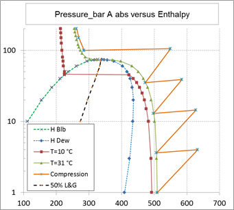
As shown on the above figure, carbon dioxide compression is started in gas phase at a pressure slightly above 1 bar abs and at a temperature of 30 °C. Should the temperature be significantly lower, there is no possibility for liquid formation (at least not below minus 50 °C).
Above 40 bar abs, the temperature has to be controlled carefully to avoid the formation of carbon hydrates (temperature to be above 20 °C providing 5 °C temperature margin in case of presence of methane in the carbon dioxide mixture) and also to avoid the liquefaction of carbon dioxide when using a compressor handling only a gas phase.
Carbon dioxide could be partially liquefied, without any risk of hydrate formation, at a temperature of 20 °C in view of using a two phase flow compressor (pump). This temperature corresponds to a liquefaction pressure of approximately 60 bar abs. The compression could operate in two phase flow up to 73 bar abs corresponding to the critical pressure above which the fluid is in dense phase condition (single phase). The pressure range in two phase flow is therefore relatively narrow.
In addition, there is a major difficulty in controlling the volume flow crossing the two phase flow pump as the liquefaction occurs at a single point condition in terms of pressure for a given temperature value (case of every pure fluid). This would induce a lack of knowledge (therefore control) in the gas and liquid fractions therefore in the total volume flow. This total volume flow could vary in the volumetric mass ratio of the liquid and gas phases that is of the order of 6.
If the fluid mixture was made of a least two pure components, the gas-liquid phase fractions would be represented by an envelope and not by a single line (pure component). In this last case the gas and liquid fractions could be controlled during the two phase compression.
As a result of these two points, the two phase flow compression (pumping) of carbon dioxide does not present a significant advantage as the domain of operation is extremely small and the liquefaction process is practically out of control.
Concerning two phase flow pump design and performance see: http://yvcharron.com/index.php/two-phase-flow-pumps/
.
For more details on carbon dioxide compression with formula and graphs get document below in pdf format.

CONCLUSION
Sonic losses may be limited by controlling the local relative gas velocity below the speed of sound at the blade leading and trailing edges. This is particularly important at low temperature.
Choke losses may be limited by controlling the gas velocity in the hydraulic cell channels particularly at low pressure and low temperature.
The operation of a carbon dioxide compression train is limited in compression range due to a limited rotating speed range. It is also limited in flow range due to, respectively, the surge and overload occurrence when the flow is slightly, respectively, reduced or increased.
The compression of carbon dioxide in a two phase flow mode does not present a major advantage as the domain of operation in pressure is extremely narrow and the liquefaction process is practically out of control.