
FLoating Houses
CONTENTS
I – Introduction
II – Basic configuration
III – Adaptation to the environmental context
– III-1 – Flood protection
– III-2 – Ground movement protection
– III-3 – Fire protection
– III-4 – Tempest protection
– III-5 – Improved comfort
– III-6 – Increasing energy efficiency
I – Introduction
In many parts of the world, habitats are subject to severe environmental constraints, particularly during natural disasters sometimes leading to significant damage or even complete destruction. Some of these upheavals have been occurring for millions of years, while others, more recent, are the result of climate change, which is itself the consequence of human activities.
Among these elements that can endanger the habitat we can cite: earthquakes, tsunamis, tidal waves, volcanic eruptions, floods, storms, fires, subduction phenomena or even land movements in the ground at foundation level.
The first four elements are the result of the surface activity of the planet (the tectonic layers) as well as that of greater depth (volcanic eruptions).
Floods occur in coastal areas but also in mountainous and plain areas, near torrents and rivers. They are largely linked to atmospheric elements and, in particular, to their irregularity (short period of heavy rainfall, storm). They are amplified by the configuration of the terrain, its constitution but also by the lunar incidence (tidal amplitude). It is now proven that their intensity tends to increase due to global warming mainly as the result of the greenhouse effect, warmer air being able to store a greater quantity of water vapour.
Fires occur at certain times of the year (especially during the summer period) and more particularly in forests providing an almost inexhaustible source of fuel. The outbreak and severity of fires intensify during periods of severe drought.
Subduction phenomena can have natural causes but can also be caused by human activities such as the exploitation of maritime sand near coastal areas causing slow sinking into the ground of nearby inhabited areas.
The constitution of the subsoil sometimes includes shallow clay layers. These layers expand during rainy periods and contract during dry periods, causing local variations in elevation and subsidence of the land, inducing strong mechanical stresses to the foundations of houses and, consequently, on all house structures (Cracking of walls).
If it is difficult to find solutions to respond to these forms of aggression for large buildings, solutions exist for individual housing. A movable support or even a floating support could help protect individual homes and even bring innovations, in particular, in terms of comfort and energy efficiency.
.
II – Basic configuration
The basic configuration includes a main reservoir (2) filled with water (8). Several vessels filled with air are submerged in this tank (one or more elements 1a and 1b) on which the structural elements of the floors (4, 5 and 6) are placed. A vertical mast (3a) buried in the ground (7) crosses the floating section as well as floors 4 to 6. A fixed ring (9) is mounted around the floating section (1a & 1b). See Figure 1 below.
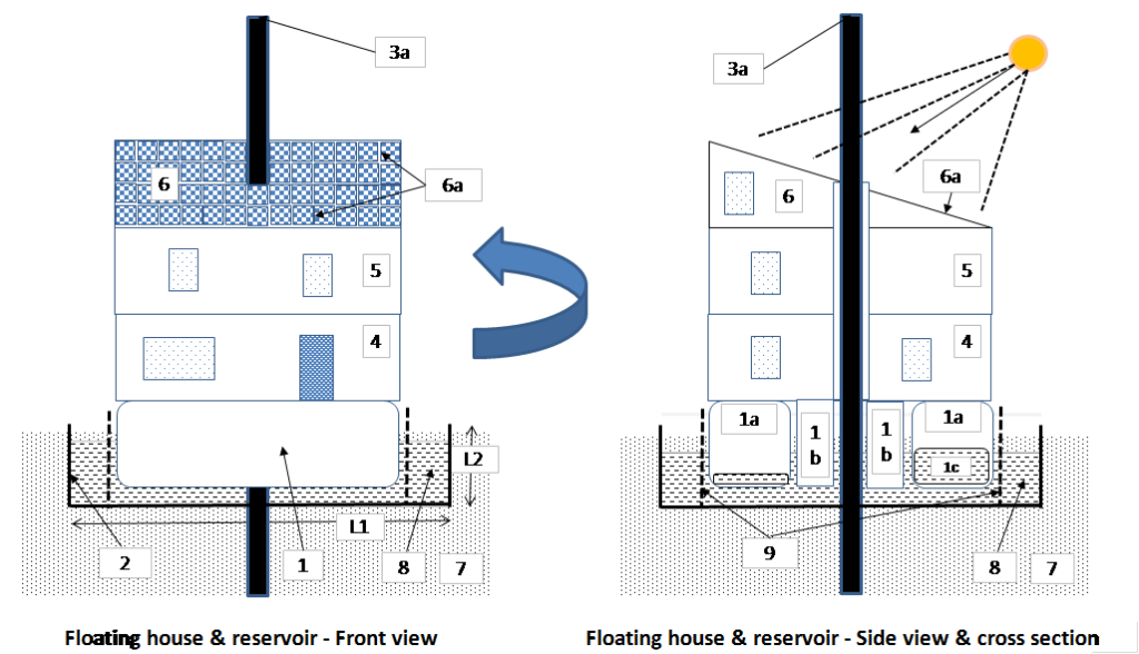
Figure 1 – Basic configuration: 1- Floating vessel; 2- Main water tank; 3a- Centring mast; 4, 5 and 6 – 1st to 3rd floor; 6a- Photovoltaic sensors, 7- Soil; 8- Tank water; 9- Crown for centring the floating vessel and for rotating the house.
.
The main reservoir can be of any cross-section (shape) while the floating section and the crown both have a circular section so that the floating section can rotate, according to comfort or sunlight criteria, around the mast and the fixed crown.
On the roof (floor 6) photovoltaic sensors are installed for electricity production. Part of the electricity produced is stored in batteries located in the floating section 1b, thus allowing a lowering of the centre of gravity of the entire floating part.
The mast can be made up of a single element 3a as shown in Figure 1 or be telescopic as shown in Figure 2 (Section III.1 Flood protection) for aesthetic reasons.
The azimuthal orientation of the floating section is determined according to comfort and electrical production criteria. During hot periods, the house could possibly be oriented in the direction opposite to the sun, giving priority to summer comfort. It will be the opposite during cold periods. For maximum electricity production, the house, and therefore the roof, will be oriented in the direction of maximum sunlight requiring relatively frequent azimuthal adjustment during the day. The control of the movement can be done manually or automatically. The rotation of the floating section is carried out mechanically using a gear system between the floating section and the crown or around the mast (Section III – Ground movement).
The flotation system preferably consists of four identical vessels (tanks 1a) mounted at 90 degrees from each other. This configuration allows mass balancing in two perpendicular directions (East-West and North-South) to be achieved by partially filling or emptying the vessels 1a. The flotation system also consists of a fifth central vessel 1b serving as a cellar. In this vessel, the heaviest or densest elements are stored, such as the batteries required for storing electricity.
Connections of utilities to the fixed soil: fresh water, waste water, rainwater, electrical wires use flexible connections.
Simplified sizing of a two floor house and a three floor house: See PDF document.
.
III – Adaptation to the environmental context
Figures 2 to 5 are summarized above and presented with details the attached PDF.
PDF on Floating houses in english
PDF sur les Maisons flottantes en français
.
III-1 – Flood protection
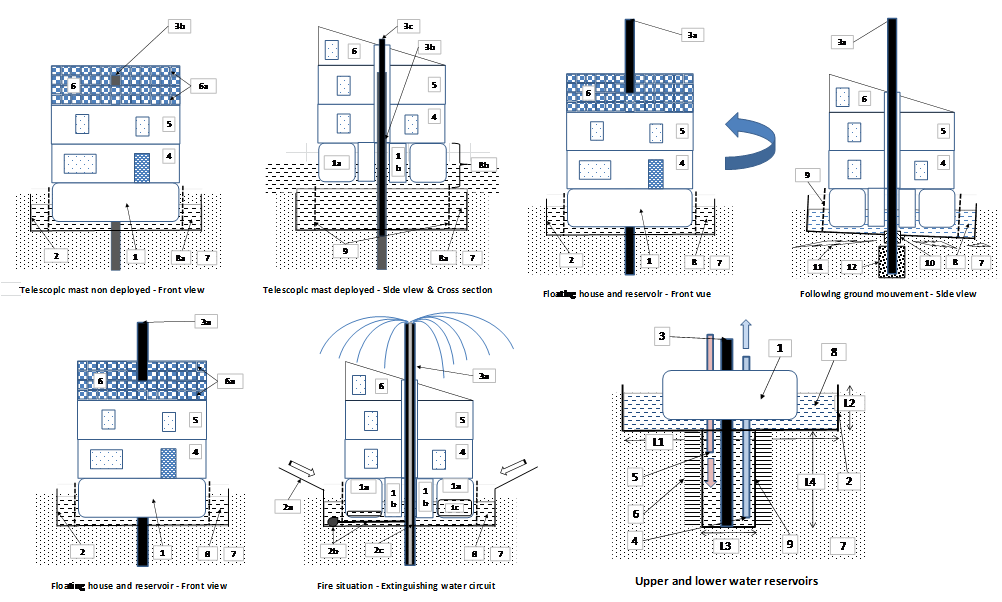
During a flood (water level increasing from level 8a to 8b), the floating section generates a buoyancy force greater than the force prior to the flood causing the home assembly to rise while maintaining the previous submergence level constant of the flotation vessel. See Figure 2 in attached PDF.
The assembly made up of the floating section and the house rises along the vertical mast (3) so as to avoid any overturning, especially in the event of a current of water with a high velocity.
For aesthetic reasons, the mast can be telescopic and made up of two concentric tubes (3b and 3c), one inner tube (3c) sliding inside the fixed outer tube (3b). The inner tube is driven using the upper part of the house (6) to which it is fixed, allowing this tube to rise or fall according to the degree of flooding.
III-2 – Ground movement protection
The mode of protection described below is designed, firstly, for movements of high amplitude and short duration representative of earthquakes of high magnitude, secondly, for slow movements of low amplitude and long duration representative of the constitution of the subsoil, in particular, clay layers as well as intermediate movements (low magnitude earthquakes).
III-2-a –Slow variation and low amplitude of ground movements
By slow variations we mean movements occurring over a time scale of the order of a month. This situation is typical of ground movements resulting from the swelling or retraction of certain layers of the subsoil. These ground movements are relatively predictable, progressive and of small amplitude. The predictive nature is possible by probing the subsoil and according to the characteristics of successive wet and dry periods. These ground movements sometimes generate severe stresses on the foundations of conventional houses which can cause significant cracks on the interior and exterior walls.
When the underground moves, the main water tank (2) is driven in the direction of the underground forces which can result in an inclination or a vertical movement of the tank. In order that the mast undergoes little movement, the latter is buried in the ground at a large depth with anchoring by an injection of concrete (12). See Figure 3 in attached PDF.
The crown around the floating section following the movements of the main tank, it is preferable, in regions subject to ground movements, to allow the rotation of the house in relation to the fixed mast and not in relation to the crown.
A deformable sealing system (10) is required at the point where the mast passes through the reservoir.
A minimum of plasticity is required on the walls of the tank so that they can deform without breaking and, consequently, allow the floating of the house which will not suffer structural damage unlike a house built on foundations.
III-2-b – Rapid variations in ground movements
By rapid variations we mean variations ranging in a time scale of a few seconds or minutes, which are difficult to predict and with very large amplitudes. This description is typical of earthquakes.
A design relatively similar to that described above (Figure 3 – See PDF) can be considered for the protection of the floating house. However, the mast will have to be buried at a greater depth and have a greater strength. Furthermore, it will be necessary to consider the destruction of the reservoir beyond a certain magnitude with total loss of the water of the main reservoir.
III-3 – Fire protection
During a fire inside or near (Example of a forest fire) a floating house, water is pumped at the bottom of the tank (elements 2b) and injected into the internal conduct (element 2c) of the centring mast (3a). The water springs back into the upper part of the mast, watering the roof of the house and falling downwards where water is collected on an impermeable inclined surface (2a) allowing its return to the main reservoir (2). As it falls to the ground, part of the water evaporates under the action of the heat, creating a cooling of the walls of the house while the other part creates a water screen around the house. See Figure 4 in attached PDF.
The recycle of the water used to extinguish the fire makes it possible to fight the fire over a longer period of time and therefore with a greater efficiency.
III-4 – Storm protection
Several actions can be taken to act against the effects of a storm predicted several hours or days before its appearance. These actions are mainly aimed at regions subject to frequent and strong storms.
Firstly, the house is oriented in a direction with less wind resistance. With this in mind, the roof is swept by the storm from the side and not from the front. We can also imagine an extension on the side of the house with a triangular or curved shape in order to provide less wind resistance (lower flow drag coefficient).
Secondly, the flotation elements are fully filled with water (1a, mainly) causing the entire floating vessels to sink so that the house height relative to ground is reduced inducing a lesser impact to the wind.
III-5 – Improved comfort
Improved comfort is mainly obtained thanks to the ability to rotate the habitat versus the cardinal points according to the seasons and the climate. In winter or during cold periods, we can benefit of the heat from the sun or an accentuation of the receiving light by orienting the living rooms in the direction of the sun, from sunrise to sunset. In summer or during hot periods, we can look for the opposite effect by orienting the living rooms in the direction opposite to the sun.
This facility will require some angular adjustments during the entire day. This process can be obtained by manual or programmed actions thanks to the current development of home automation.
It should be noted that these orientation expectations must be taken into account with the energy efficiency criterion. It is relatively obvious that in winter, seeking out the sun’s rays will satisfy both comfort and energy efficiency criteria. In summer, a compromise will be necessary by giving priority to either comfort or electricity production. This adaptation will be the result of an analysis of several parameters: local temperature, time of the day, existence of an energy storage and present energy requirement.
Thermal comfort and energy efficiency may be both improved according to the capacity and the design of the water tank. Indeed, the greater the water reservoir volume and the greater the reservoir depth, the more the thermal comfort of the habitat and the energy efficiency are increased as shown in the following section.
For another comfort perspective, the tank can be used as a swimming pool.
We can also imagine a utilitarian aspect to the water tank by designing it for fish farming.
It is worth noting that the pumping system described in the fire section can also be used for the recycling of water either in a recreational setting (swimming pool) or for the oxygenation of water (fish farming), especially in summer time.
III-6 – Increasing energy efficiency
Two parameters can contribute to improving energy efficiency. The first relates to the storage of water in a reservoir and the second to the production of electricity by photovoltaic sensors and by the storage of this energy.
III-6-a – Water storage and heating with heat pump
The water contained in the main tank, largely buried in the ground, has a temperature close to that of the ground when the water is not directly in contact with the ambient air. As a result, in summer, the water temperature is lower than that of the air and, in winter, it is higher. We can consider that a large fraction of the time, the temperature is between 10 and 20°C, especially when the water is not in direct contact with the air (upper part of the tank covered).
In this situation, the use of a heat pump using tank water as a source of heat (winter) and a source of cold (summer) is particularly recommended. In winter time, the temperature rise required by the heat pump will be low, especially if the house has heated floors (large exchange surface and very low temperature rise required). In summer time, the temperature reduction required by the heat pump will be even lower, the water temperature being close to the comfort temperature.
Energy efficiency can also be improved by installing a second reservoir, in the form of a well, under the main reservoir allowing even lower variations in water temperature between the hottest and the coldest seasons. The average reservoir water temperature would be around 15°C when the heat system is at rest. When the heat pump is active, this temperature tends to increase in summer and decrease in winter following the transfer of heat in summer and cold in winter (from the house to the tank). To maintain the temperature of the lower tank in a close range, a heat conduction system is provided outside the second reservoir (well), between the walls of the reservoir and the ground. See figure 5 in attached PDF.
III-6-b – Photovoltaic sensors and roof design
The roof is made up of a single slope, unlike conventional houses, in order to increase the surface area for capting solar energy, thus allowing a doubling of the energy capted (Figure 1).
The floating house can be oriented as desired, from east to west, allowing optimum captation of solar energy. The energy capted by an adjustable roof (house) orientation is approximately 50% higher than that capted by a fixed roof.
All of these two parameters allow an electricity production of around three times compared to that of a conventional house representing an increase of 200%.
The energy capted and not consumed is stored in the battery pack located in the cellar (element 1b – Figure 1).
Leave a Reply