
Keywords: gas treatment sour acid physical chemical solvent multiphase turbine let down valve
1_ Introduction
Processing of a gas, for example, natural gas, synthesis gas, combustion gas, gas from integrated combined cycles, generally involves removal of impurities such as nitrogen (N2), ammonia (NH3), and acid compounds such as carbon dioxide (CO2), hydrogen sulfide (H2S), sulfur dioxide (SO2), COS, CS2 and mercaptans. These impurities are present in various proportions depending on the origin of the gas. In the case of natural gas, CO2 and H2S can be present as traces, some ppm, but they can also represent a quite significant proportion of the raw gas, up to 70% by volume. Other impurities such as COS, CS2 and mercaptans can also be encountered, generally, a few thousand ppm.
According to the initial proportions of impurities in the gas to be processed, and also according to the specifications required for the processed gas, various scrubbing processes are used. Most gas treatment processes use solvents. These solvents can be of physical or chemical nature. Solvents of physical nature are based on the preferred solubility of the impurities in the solvent and are therefore favoured by the high partial pressures of the impurities in the gas to be processed. Solvents of chemical nature are ideally used to reach the strictest specifications for the processed gas, by chemical consumption of the species absorbed by reaction with an active agent contained in the absorption solvent. There are also solvents of hybrid nature consisting of a mixture of physical and chemical solvents so as to cumulate the advantages of these two solvents.
Whatever the origin of the gaseous effluent to be processed, the purification loop generally consists of an impurities collection stage using a solvent and of a solvent regeneration stage. The regeneration stage is conditioned by the nature of the solvent used. In the case of a solvent involving a chemical reaction, a thermal regeneration is generally used to obtain a sufficient solvent purity allowing the desired specifications to be reached. Thermal regeneration can be preceded by regeneration by expansion in order to limit the energy required for thermal regeneration. In the case of a solvent of hybrid or physical nature, regeneration is essentially carried out by expansion, possibly completed by a thermal regeneration stage.
The present document describes the improvement of solvent regeneration. It results from the expansion of laden solvents through two-phase turbines instead of letdown valves. This improvement is particularly significant with physical (or hybrid) solventsand with two phase turbines of the rotodynamic type.
_
2_ Gas treatment principle and variants
The treatment process is applied to a gas comprising various types of impurities. These latest may be CO2, H2S, SO2, COS, CS2, mercaptans, N2 and NH3.
2-a – BASIC CONFIGURATION – The treatment process is carried out with the use of a single two-phase turbine section through the following steps:
a) contacting the gas with a solvent absorbing the impurities so as to obtain an impurity-laden (charged) solvent and a scrubbed (cleaned) gas. The solvent may be of a physical or hybrid nature.
b) expanding the impurity-laden solvent through a two-phase turbine so as to release an amount of impurities in gaseous form and to obtain an impurity-depleted solvent. The two-phase turbine section may be of a rotodynamic type comprising one or several stages, each stage including one impeller (rotating element) and one diffuser (fixed element).
c) separating these impurities from the impurity-depleted solvent.
2-b – VARIANT 1 – Depending on gas characteristics and separation efficiency requirement, the system may include two additional steps:
d) expanding the solvent outleting the separation vessel c) through a second two-phase turbine section so as to release a second amount of impurities in gaseous form and to obtain an expanded solvent in a more purified condition. As per step b), the two-phase turbine used in this step d) may comprise one or several stages. The two turbine sections may be mounted on a single shaft and in the same casing.
e) separating the second amount of impurities from said expanded solvent.
2-c – VARIANT 2 – The regeneration cycle may be improved by using the following steps:
f) distilling said impurity-depleted solvent so as to separate the impurities from the solvent,
g) recycling the distilled solvent to step a).
The contacting vessel used in step a) can operate at a pressure ranging, in most cases, between 1 MPa abs. and 15 MPa abs. while in step b) the solvent can be expanded to a pressure ranging between 0.1 MPa abs. and 3 MPa abs.
_
3_ Detailed description
3-a – Basic configuration with a single two phase turbine section
The operating principle of this configuration is presented in figure 1. The gas to be processed (comprising impurities) flows through line 10. It is possibly cooled in heat exchanger E1 then fed through line 11 into absorption column C1. The gas is then contacted with a liquid solvent fed through line 18 into the top of column C1. The solvent absorbs the impurities contained in the gas. The scrubbed gas, i.e. depleted in impurities, is discharged at the top of column C1 through line 19.
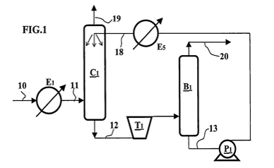
Figure 1 – Gas treatment in basic configuration
The solvent can be of physical or chemical nature. For example, it may be an alcohol, a glycol, a heavy hydrocarbon such as propylene carbonate, a potassium carbonate, a morpholine, a polyethylene glycol dimethylether, an amine such as an alkanolamine or an alkylamine. The solvent can also be a mixture of two or more aforementioned solvents.
The liquid impurity-laden solvent is discharged from column C1 through line 12 then expanded in two-phase turbine T1. The expanded solvent is fed into separating drum B1. The impurities released in gaseous form upon expansion are discharged at the top of drum B1 through line 20.
The liquid solvent recovered at the bottom of drum B1 through line 13 is depleted in impurities. It can be pressurized by pump P1 then fed through line 18 to the top of column C1. Expansion in turbine T1 presents the advantage of cooling the solvent. However, if the regenerated solvent is not sufficiently cold, it can be super cooled by heat exchanger E5 prior to being fed into column C1.
3-b – Variant 1 using an additional two phase turbine section
The operating principle of this configuration is presented in figure 2. The stages carried out in exchanger E1, column C1, turbine T1 and drum B1 of figure 2 are identical to the stages carried out in figure 1.
In figure 2, the liquid solvent coming from the bottom of drum B1 through line 13 is expanded in two-phase turbine T2. The expanded solvent is fed into separating drum B2. The impurities released in form of gas upon expansion are discharged at the top of drum B2 through line 21. The liquid solvent recovered at the bottom of drum B2 through line 14 is depleted in impurities. It can be pressurized by pump P2 (not represented) then fed through line 18 to the top of column C1.
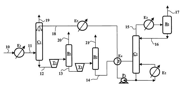
Figure 2 – Gas treatment with variants 1 and 2
3-c – Variant 2 using a distillation column
Expansion in turbine T2 is optional, which means that, in the method described in connection with figure 2, elements T2, B2 and 21 can be removed and line 13 can be directly connected to line 14.
The liquid solvent recovered at the bottom of drum B2 through line 14 is depleted in impurities. It is heated up in heat exchanger E4 then fed into distillation column C2. The distillation column allows to carry out advanced regeneration of the solvent, i.e. to reduce the proportion of impurities in the solvent to a very low level, in any case to a lower level than that obtained by means of regeneration by expansion. Reboiler E2 provides the heat required for distillation in column C2. The gas phase discharged at the top of column C2 through line 15 mainly comprises impurities. This gas phase is partly condensed by cooling in heat exchanger E3 then fed into separating drum B3. A gas phase mainly comprising impurities is discharged from drum B3 through line 17. The condensates recovered at the bottom of drum B3 are injected through line 16 to the top of column C2 as reflux.
The regenerated solvent available at the bottom of column C2 is pumped by pump P1, cooled in heat exchanger E4, then injected to the top of absorption column C1. Expansion in turbines T1 and T2 has the advantage of cooling the solvent. Thus, the solvent obtained after expansion constitutes a coolant for cooling the regenerated solvent intended to be fed into column C1. However, if the regenerated solvent is not sufficiently cold, it can be super cooled by heat exchanger E5 prior to being fed into column C1.
_
4_ Benefit of two phase turbines
In the methods described in connection with figures 1 and 2, expansion of the solvent is carried out by means of two-phase turbines T1 and T2. These turbines are of the rotodynamic type and more precisely of the helico axial type. This turbine type provides the following advantages:
- The pressure let down through turbines allows to release impurities in a gaseous form.
- Expansion of the solvent by means of a turbine is accompanied by a temperature reduction of the solvent due to an expansion of the gas produced during the letdown. As a first approximation, expansion by means of a turbine is close to an isentropic process. This cold production allows to compensate for the temperature increase in the absorption column during the absorption reaction which is generally exothermic.
- From the above it results that the use of two phase turbines permits to cancel or reduce the demand for an external cooling. The system may be designated as an auto thermal process. For example, when the solvent is regenerated only by expansion, the solvent obtained after expansion requires no or only a low temperature reduction before injection of the solvent into the absorption column. Similarly, when the solvent is regenerated by expansion and distillation, the solvent obtained at low temperature after expansion constitutes a coolant allowing to cool the high-temperature regenerated solvent from the distillation column.
- Expansion energy may be recovered at the shaft end of the two-phase turbine. This energy may be used for driving the solvent pump P1 and/or for recompressing the impurities in gaseous form circulating in lines 20 and 21 at the outlet of drums B1 and B2.
The two-phase turbines mentioned in the above processes are of the rotodynamic type. As a consequence, they can handle, mechanically wise, all gas fraction values (from 0 to 100 %) produced during solvent expansion. This mechanical property is generally not attributed to volumetric turbines (piston, gear).
During solvent expansion the gas fraction varies largely. It increases from 0% at turbine entrance (solvent strictly in a liquid phase condition) to a high gas fraction for which the value depends on the gas and solvent characteristics but also on the expansion conditions (pressure and temperature). The large gas fraction increase during solvent expansion corresponds to a large volume flow increase from the turbine entrance to its exit. This requires some geometrical adaptation at each hydraulic stage (impeller and diffuser) resulting with small dimensions at the inlet and large ones at the outlet. At the first stage, the impeller diameter is relatively small well adapted to the compression of a mixture with a large molecular weight (low gas fraction). To the contrary, at the last stage, the impeller diameter is relatively large well adapted to the compression of a mixture with a low molecular weight (large gas fraction) Geometrically wise, the rotor of the turbine presents some sort of conical shape with the impeller diameter increasing continuously from turbine inlet to outlet.
_
5_ Conclusion
The replacement of letdown valves by two phase turbines in a gas treatment system presents numerous advantages: a) the letdown of a laden solvent permits to release the impurities in a gas form; b) the release of this gas phase during let down generates an expansion of the gas providing some cooling of the solvent; c) the solvent regeneration approaches an auto thermal process; d) with the use of a distillation tower, the purified solvent may be cooled at the outlet of the boiling phase; e) the energy produced during the two phase expansion of the laden solvent may be used for pumping the solvent or for compressing the gas containing impurities.

_