
Keywords: Structured surfaces two_dimension 2D 3D drag reduction summary manufacturing applications
This section deals with a reduction in aerodynamic drag by controlling the flow in the turbulent underlay using a particular form of surface geometry. In an internal flow (case of a pipe), this reduction in the activity of the turbulent sub-layer results in a reduction in pressure loss while in an external flow (case of an airplane wing) by a decrease in the drag force. Three forms of structured surfaces from three successive generations are presented in this section.
Flow drag reduction mechanisms
First flow drag reduction mechanism
The first method known since the 1940s uses fine grooves oriented longitudinally in direction of the flow, the width and the height of the grooves being close to the thickness of the viscous layer. This method was developed following the observation of the constitution of the skin of sharks, having micro grooves in direction of their displacement, allowing them to move in water relatively quickly. This is the reason why these grooves are sometimes called riblets or sharklets. This configuration is also called two-dimension grooves as opposed to the more complex grooves presented in the following paragraphs. These grooves allow a reduction in drag (aerodynamic or hydraulic) of the order of 5 to 10% depending on the transverse shape of the grooves (triangle, half ellipse or knife blade).
For more details: http://yvcharron.com/index.php/two-dimension-structures/
Second flow drag reduction mechanism
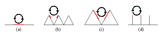
The second method, developed in the 2000s, combines the principle of two drag reduction phenomena, the first one being the use of a conventional structured surface oriented longitudinally in the direction of the flow. The second one is based on the observation of a reduction in the drag in the flow direction following a transverse oscillation of the wall at the origin of this drag. As this second method cannot be implemented directly in a fixed pipe, it has been the subject of a transposition of the movement of the wall by the contribution of a transverse undulation of the grooves inducing an undulation of the flow. These “oscillating” grooves allow a reduction in drag of 12 to 20% depending on the basic shape of the grooves (triangle or knife blade) and in the case of an optimized transverse undulation of the grooves. These grooves will be designated by a three-dimensional type 1 shape.
For more details: http://yvcharron.com/index.php/three-dimension-structured-surfaces-type-1/
Third flow drag reduction mechanism
The third method, developed shortly after the second, uses the two phenomena of drag reduction mentioned above, to which is added a re balancing of the turbulent control forces and viscous losses along the “oscillating” groove. This re balancing, itself oscillating, is established in the radial direction (perpendicular to the wall) and at a frequency twice that of the transverse oscillation. On the physical level, this is characterized by an increase in the height of the grooves at the point of maximum inflection (left and right peaks in the transverse oscillation) and by a reduction in the height of the grooves at the point of minimum inflection (change in concavity in the transverse oscillation). On a mathematical level this may be figured out by the addition of a radial oscillation, orthogonal to the transverse one with a frequency twice of the first one compared to the second one. These grooves would provide a reduction in drag of 20 to 30% depending on the basic shape of the grooves and in the case of optimized radial and transverse undulations. These grooves will be designated by a three-dimensional type 2 shape.
For more details: http://yvcharron.com/index.php/three-dimension-structures-type-2/
Towards a fourth flow drag reduction mechanism
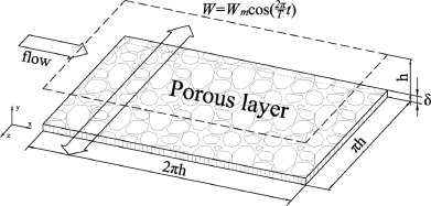
To the last flow drag reduction mechanisms (3D-2, above paragraph) could be added a fourth one, for instance, another geometrical feature or a compliant coating or a porous coating. On the figure below a four mechanism system is represented with the span wise periodic movement and the porous wall. For clarity, the riblets and the normal periodic movement have been represented on that figure.
Industrial applications
This section presents some examples of industrial applications of structured surfaces provided on the surface of elements in relative motion with respect to a fluid. They may be encountered in a lot of internal and external flow applications. They may be used in pipelines carrying liquid or gas and in the internals of large rotating machines (compressors, pumps or turbines). Concerning external flows, they may be used in several means of transport: planes, trains, boats but also on airplane wings or wind turbine blades.
This will be presented later.
Groove manufacturing
This section also presents means for manufacturing grooves on the surface of elements in relative movement with respect to a fluid with a view to reducing the drag forces. This will be presented later.