
Keywords: Fossil fuel power plant carbon dioxide captation energy recovery stoichiometric combustion compression expansion
Large power plants
Large power plants provide electricity from nuclear, coal or hydrocarbon energy sources using electric generators driven by steam or gas turbines. These forms of energy present their own advantages and own drawbacks. In all cases, the thermal efficiency is relatively low with a lot of heat rejected into the atmosphere. In addition, in the case of coal and hydrocarbons several types of pollutants are rejected into the atmosphere. The present document addresses the gas turbine case proposing some solutions to improve the overall thermal efficiency and to permit captation of sour gases, particularly, carbon dioxide and nitrogen oxides. These solutions may also be suitable in most cases to coal applications.
A gas turbine (combustion turbine) is a thermodynamic machine providing mechanical power. It operates generally in an open cycle with internal combustion. Despite its terminology, the machine can use either gas or liquid fuels. It operates according to the Brayton cycle: air admission followed by air compression (1 to 2 – figure below), air heating (2 to 3); hot air expansion (3 to 4) and heat rejection at ambient pressure.
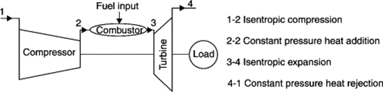
The thermal efficiency (ratio between the mechanical energy and the combustion heat) increases with the compression ratio and the combustion temperature. Several means exist to improve the thermal efficiency like: heat recovery at the gas turbine exhaust or use of a closed cycle using a secondary fluid. For more details, see the attached document (PDF).
There are two main types of gas turbines differing by their mode of construction: the aero derivative and the heavy duty (or industrial) turbines. Aero derivative turbines use a central core engine derived from the aircraft industry (jet engine) discharging hot gases with high momentum into a last turbine stage named Power turbine. The aerodynamic design provides relatively high thermal efficiency (from 35 to 40%). Some examples of aero derivatives turbines:
https://en.wikipedia.org/wiki/Rolls-Royce_RB211 ; also
https://en.wikipedia.org/wiki/General_Electric_LM6000
Industrial gas turbines differ from aeronautical designs in that frames, bearings and blading are of heavier construction. They include only one driving shaft from the compression end (air entrance) to the expansion end (air release to atmosphere) preventing speed adaptation to the different turbine elements. As such, the gas turbine efficiency is generally smaller (30 to 35%). These turbines are often used in a combined cycle significantly improving the efficiency of the whole system. A Siemens SGT5-4000f Heavy Duty gas turbine is presented on figure below.
Ihttps://new.siemens.com/global/en/products/energy/power-generation/gas-turbines/sgt5-4000f.html
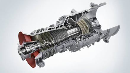
Due to their relatively small thermal efficiency characterised by a high exhaust temperature and a large amount of rejected heat, Heavy Duty gas turbines are good candidates for the process system proposed in this document.
A gas turbine providing a mechanical power of 39.7 MW with an exhaust temperature of 503 °C and a thermal efficiency of 32.5% is taken as an example in this document. The study is also conducted for two other values of exhaust temperature, 450 and 550 °C, representing the exhaust temperature range of most gas turbines. For more details on gas turbines, see the attached document (PDF).
Gas turbine assembly and associated units
In the present design, the large quantity of heat (at high temperature), usually released to the atmosphere is used to boost the exhaust gas to a gas treatment unit operating at high pressure in order to dissolve the sour gases into a physical solvent. In addition, the residual heat is used to activate a motor cycle. See figure below representing the overall system assembly.
In order to boost the largest fraction of carbon dioxide into the treatment unit without entraining any oxygen molecule, the exhaust gas is recycled (after cooling) towards the gas turbine inlet in order to provide a strictly stoichiometric combustion (oxygen molecules matching hydrocarbon molecules relatively to their number). As a consequence, the gas leaving the turbine exhaust contains mostly nitrogen, carbon dioxide, a small amount of argon and nitrogen oxides and traces of other molecules like xenon and krypton.
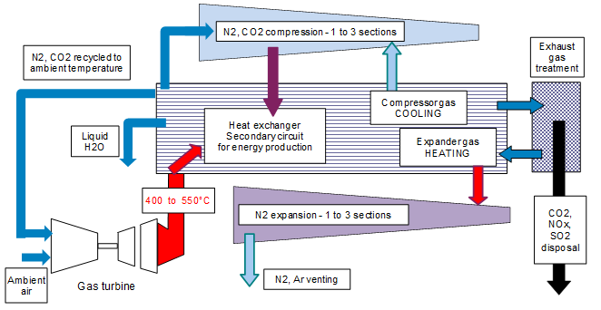
The boosting of the gas fraction is carried out by a compression unit including up to three sections. After gas treatment, the high pressure gas is let down in an expansion unit including also up to three sections, the expander unit driving mechanically the compression unit. In order that the compression unit absorbs the minimum power, each compressor inlet is cooled down to ambient temperature. To the contrary, in order that the expansion unit provides the maximum power to the compression unit, each expander inlet is heated up to the turbine exhaust temperature.
In summary, the system includes, outside the gas turbine and treatment units, two main energy based circuits, designated as follows: the “Primary Circuit” (sour gas boosting to high pressure followed by let down) and the “Secondary Circuit”, a motor cycle providing additional energy to the main turbine. Both the Primary and Secondary circuits are activated by the large heat flux at hight temperature released into the atmosphere by the gas turbine.
Gas recycling in the gas turbine unit
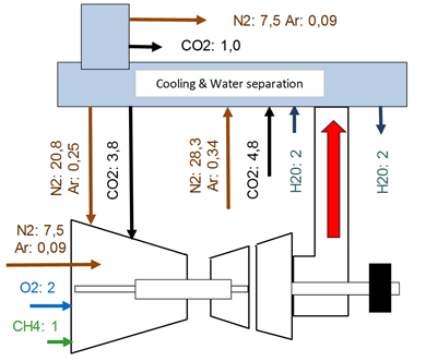
Contrary to reciprocating engines, gas turbines operate with an excess of air. As an average, the number of oxygen molecules is 3 to 5 times greater than the number required to produce a stoichiometric combustion. Compared to a stoichiometric combustion, the number of carbon oxide, nitrogen oxide and water vapour molecules are unchanged while the number of nitrogen and argon molecules is proportional to the amount of oxygen entering the gas turbine inlet (air dilution).
In order to boost the largest amount of carbon dioxide into the treatment unit without any entrainment of oxygen molecules, a fraction of the exhaust gas is recycled towards the gas turbine inlet. As a consequence, the gas leaving the turbine exhaust contains mostly nitrogen and carbon dioxide. The molecule fraction for each component is presented in the figure below.
Compression and expansion units – Primary circuit
Description of the system – It includes compression and expansion units interchanging potential energy (compressor pressure rise beneficial to the expansion unit) and mechanical energy (expansion power transmitted to the compression unit). These units including several sections, the compression unit (therefore sections) has to operate at the lowest temperature to minimize the absorbed power and to provide the highest discharge pressure. The gas is therefore cooled down at each section inlet. To the contrary, the expansion unit (sections) has to operate at the highest temperature to maximize the generated power. The gas is therefore heated up to the gas turbine exhaust temperature.
Types of compression and expansion modes – Calculations have been performed with the following data: concerning the GAS TURBINE: 2.6 kg/s fuel gas; 47.0 MJ/kg heat rate; 122 MW combustion heat; 32.5 % thermal efficiency; 39.7 MW mechanical power; 82.3 MW rejected heat. Concerning the COMPRESSION UNIT:Mass flow rate – 41.6 kg/s; Mol. Weight – 30.0; Polytropic efficiency: 85%. Concerning the EXPANSION UNIT: Mass flow rate – 34.4 kg/s; Mol. Weight – 28.1; Polytropic efficiency: 90%
Semi theoretical cases – To better analyse the effect of polytropic and semi thermal compression and expansion, assumptions have been made, first, of no intermediate pressure nor heat losses.
When all processes are polytropic, the same operating condition is met whatever is the number of compression and expansion sections. In that case, the pressure ratio is equal to 8.12 (8.12 bar abs discharge pressure) and the equilibrium power is met at 15 % of the rejected heat (31 % of the gas turbine mechanical power).
When the compression unit operates in a semi isothermal condition, the pressure ratio is increased to 20.6 and the balanced power to 16.3 MW by doubling the number of sections. The pressure ratio is increased to 35.0 and the balanced power to 18.2 MW by tripling the number of sections. The effect of the number of sections is therefore extremely important on both, the pressure ratio and the gas treatment operation.
When both the compression and expansion units operate in a semi isothermal condition (inlet temperatures of, respectively of 40 and 550 °C), the pressure ratio is increased to 65.8 and the balanced power to 25.0 MW by doubling the number of sections. The pressure ratio is increased to 536 and the balanced power to 37.5 MW (Roughly gas turbine mechanical power) by tripling the number of sections.
The same exercise has been carried out for three different expander inlet temperature values: 550, 500 and 450 °C, showing the extremely large effect of the exhaust temperature on the pressure ratio. For more details on these calculations, see the attached document (PDF).
Real case and variation of a few parameters – The above calculation was then performed taking into account for some losses, particularly, pressure drops and heat losses when passing from one section to another. It has been performed for the above three expansion temperatures, the compression and the expansion units operating in a semi isothermal condition. The same exercise was repeated by doubling and tripling the pressure losses.
The above calculation was then carried out by increasing the compression efficiency (from 85 % to 90 %). and the expansion efficiency (from 90 % to 95 %). These calculations are assumed to be applicable to very large power plants, for instance, above 200 MW whatever, it is a single gas turbine or an association of gas turbines.
To give some order of magnitude, exhaust temperatures of 550, 500 and 450 °C provide pressure ratios of, respectively, 200, 100 and 50. However, each application should be studied specifically. For more details concerning the calculation results see the attached document (PDF).
Gas treatment unit with sour gas captation
Following final compression and before entering the first stage of the high pressure expander, the gas is cooled down and sent to a high pressure separator (contactor) to dissolve the sour gas in a physical solvent. This solvent may be water, methanol or other types of physical solvent. Fine droplets of solvent are injected into the separator to absorb the sour gas. These droplets then fall down at the bottom of the separator. In a separate chamber, the solvent is heated up to release the sour gas maintaining the sour gas pressure roughly constant. Then the purified solvent is re-injected into the separator for further sour gas contacting. In the case of a 550 °C exhaust temperature, considering the 31 MW absorbed by the compression unit, 5.3 MW correspond to the boosting of sour gases to a pressure of 225 bar abs. For the other exhaust gas temperatures see the attached document (PDF). For an overview on physical solvents see:
Science Direct Topics :
https://www.sciencedirect.com/topics/engineering/physical-solvent
For more information on sour gases dissolution in physical solvent, see:
https://bre.com/PDF/A-Comparison-of-Physical-Solvents-for-Acid-Gas-Removal-REVISED.pdf
Also: Acid Gas Cleaning using DEPG Physical Solvents – AspenTech
Secondary system for energy recovery
Heat available at each compression and expansion section outlet and also the residual heat of the exhaust gas (not transmitted to the expansion unit) are used to activate a motor cycle. Note that the above sentence represents some sort of mathematical approach. In reality, no heat is removed at expander section outlets (corresponding to a higher residual heat flux from the exhaust gas for the motor cycle). In a real situation, the outlet of an expander section is heated up upstream the next expander inlet (except for the last section). However, both the mathematical and physical approaches provide the same result. For thermodynamic motor cycles:
https://en.wikipedia.org/wiki/Thermodynamic_cycle
The motor cycle is a classical system including four elements in which a refrigerant fluid circulates in a closed loop: a pressurizing liquid pump, an evaporator, an expander and a condenser.
Calculations have shown that the Carnot efficiency corresponding to the heats taken out from the compressor unit is 36 % (259 °C – heat recoverable 27.3 MW), from the expansion unit is 34 % (240 °C – heat recoverable 21.5 MW) and from the residual heat is 59 % (522 °C – heat recoverable 32.5 MW). To determine the recoverable energy, a factor of 0.5 has been applied on the above Carnot efficiencies. It results that a power of 18 MW could be recovered from these residual heats. This represents 46 % of the mechanical power delivered by the main gas turbine. For Carnot efficiency and cycle:
https://en.wikipedia.org/wiki/Carnot_cycle
Calculations have also been performed for 500°C exhaust gas temperature (15.3 MW recoverable) and 450°C exhaust gas temperature (12.6 MW recoverable).
For more details on this document see the following PDF

Conclusion
The heat released by a combustion (gas or liquid) turbine to the atmosphere is extremely large, 60 to 70% of the combustion heat. This percentage depends on the gas turbine type (aero derivative or heavy duty).
This large amount of heat could be converted into energy, firstly, to boost sour gases to a high pressure level (“Primary Circuit” for gas treatment) and, secondly, to activate a motor cycle (“Secondary Circuit”) providing additional energy to the gas turbine.
In the case of an exhaust temperature of 550 °C, from the 82.4 MW rejected heat, 5.3 MW (6% of the rejected heat) could be produced to rise to 220 bar the pressure of the gas to be treated (sour gas separated from the boosted gas) and an additional 18 MW (20 % of the rejected heat) to the 39 MW mechanical power of the main gas turbine.
To determine the recoverable energy, a correction factor of 0.5 has been applied to the calculated Carnot efficiencies. More work is required to determine the exact power recoverable based on more accurate Carnot efficiencies.
This study was initiated by Yves CHARRON in 2005 at IFP. Calculations were reviewed in 2020.
http://yvcharron.com/index.php/contact/

Keywords: Fossil fuel power plant carbon dioxide captation energy recovery stoichiometric combustion compression expansion