Keywords: helico axial two-phase flow turbine energy recovery effluent cooling liquid velocity control
Two phase flow expansion – Conventional equipment
The petroleum, refining and petrochemical processes involve numerous energy conversions, whether in terms of compression or expansion. Often, when the energy levels are low, the expansion is carried out through a let down valve to avoid the use of expensive rotating machinery. When the energy balance is greater, the expansion takes place in monophasic conditions in two parallel branches requiring many equipment: a vessel separating the liquid and gas phases upstream the expansion, an expander for the gas expansion and a turbine for the liquid let down.
Two phase flow expansion – Benefits
The expansion of the gas allows the recovery of a large amount of energy (compressible fluid) unlike that of the liquid (incompressible), the enthalpy variation of a gas being considerably larger than that corresponding to the expansion of a liquid for the same initial and final pressure values. Furthermore, the expansion of a gas is accompanied by some cooling allowing the condensation of the less volatile elements. The liquid phase produced as a result of the gas expansion is very often of a great financial value as it is more easily transportable than the gas.
Two-phase expansion through two phase machinery responds to this problem. It allows through a single device instead of three (separator, liquid let down and gas expander) the expansion of a two-phase mixture allowing both energy recovery and the partial conversion of the gas phase into liquid.
Examples of a two-phase turbines are given in chapter 3 Two Phase Machinery.
Just like compressing a two-phase mixture using conventional monophasic machines which is totally ineffective apart from gas rates close to 0 or 1 (GLR close to 0 or tending towards infinity), two-phase expansion is strongly penalized by the use of radial or axial machines. There is however a counterexample provided by the expansion of liquefied natural gas where the liquid is largely vaporized inside a radial cell, but this is not a multi-stage two-phase expansion system.
Helico axial turbine – First generation hydraulic
In order to allow two-phase expansion in a multi-stage system, helico axial hydraulic cells can help to improve the meagre performance obtained using conventional single-phase machines.
Both two-phase compression and expansion using helico axial cells greatly reduce the separation forces in the three directions of an orthonormal system: in the direction of the flow (diffusion), transverse to the blades (flow rotation) and radial (resulting from the centrifugal component). It should however be noted an important difference between compression and expansion where the inertial forces play an important role in the second case allowing less slippage between the liquid and gas phases. This factor contributes to give better two-phase performance in expansion mode compared to compression mode.
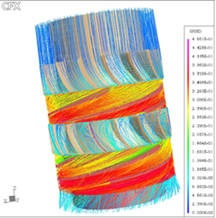
Helico axial turbine hydraulics were developed in the 2000s and have been tested with particularly satisfactory results.

This helico axial hydraulic cell can be designated by “First generation cell”. It should be emphasized that this cell is strictly axial (cylindrical) on its external part.
This section will be completed in 2020 with a more detailed report on the first generation two-phase turbine.
Helico axial turbine – Second generation hydraulic
Just as the second generation of compression hydraulics allows interfacial slip control (velocity of the liquid phase approaching the one of the gas phase), it is perfectly conceivable to apply this theory to the impeller of a hydraulic turbine. This should also lead to a slightly radial shape.
http://yvcharron.com/index.php/two-phase-flow-pumps/
On the other hand, contrary to the compression impeller having an increasing diameter from the entry towards the exit, the expansion impeller must present a decreasing diameter from the entry towards the exit so as to take into account all the forces driving (inertial force) and braking the displacement. The components of the braking forces would be at least two in number: the viscous force (viscosity and density) and the residual component of the centrifugal and centripetal forces.
By adopting the same definition of interfacial slip, we can designate this expansion impeller by “Interfacial Slip Control” (ISC) or “Phase Velocity Control” (PVC). This helico “quasi-axial” hydraulic cell can be designated by “Second generation cell”.