1_Introduction
Heat is currently recovered from the ground by conventional geothermal production systems extracting hot water stored at large depth. In most cases, water is available at medium temperature (between 50 to 100 °C depending on reservoir characteristics) which is sufficiently high to supply heating to residential areas. In other cases, water pressure and temperature are considerably greater providing high pressure steam together with hot water. In these cases, energy may be recovered by the use of a steam turbine. Following treatment, water is disposed at the surface or re-injected into the ground depending on water properties and local regulation.
Carbon dioxide is detrimental to the environment. As a consequence, this gas is occasionally injected into the ground for long time storage.
Carbon dioxide storage and heat available into the ground are two parameters that have to be considered for energy supply. This could be performed by using a geothermal loop extracting the gas from a storage cavity, energy and heat being recovered on the surface with the gas re-injected into the ground. Operating such a system with any gas would not provide necessarily any benefit when the energy required to re-inject the gas may be more or less equivalent to the energy recovered at the surface.
Carbon dioxide thermodynamic properties are determinant to provide a positive energy balance in a geothermal loop
2_Description of the system
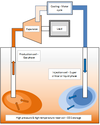
The system consists in a carbon dioxide geothermal loop including at ground surface a gas expander with cooling devices, a well for injecting the dense fluid into a reservoir and a second well supplying a hot pressurised gas to the expander. In between these two wells, carbon dioxide is stored in a high pressure and high temperature reservoir.
Following gas cooling (below 30 °C) downstream the expander, carbon dioxide is either in a liquid or a super critical phase condition characterized by a large volumetric mass (approx. 1000 kg/m3). The fluid is discharged, through the injection well, into the high pressure and high temperature reservoir where heat is progressively transferred to the newly injected fluid. Production and injection wells are sufficiently remote in order that the newly injected carbon dioxide mass does not reach the production well in a too short time therefore at a temperature lower than the reservoir temperature. Carbon dioxide is supplied by the production well at a high temperature (for instance 150 °C) in a gas phase condition with a medium volumetric mass (for instance 500 kg/m3).
Considering the difference in volumetric masses, the pressure at the production well is significantly greater than the one at the injection well, the difference in pressures increasing with the well length and the reservoir temperature. This difference in pressure may be used to activate an expander transmitting energy to a load: an electric generator or a mechanical machine (compressor or pump).
The cooling provided by gas expansion being not sufficient to reach liquid condition, the gas is further cooled in one or several external cooling devices.
3_ Reservoir characteristics
An indication of reservoir temperature is given by:
https://www.sciencedirect.com/topics/engineering/reservoir-temperature. According to this document, the reservoir temperature could be estimated by adding the surface temperature to a temperature gradient ranging from 0.5 °C (minimum) to 0.9 °C (maximum) per 30 m. This gradient would be valid for most reservoirs. However, there are anomalies where this gradient may be considerably larger. The gas expansion (according to an isentropic process) occurring during its displacement from the reservoir to the surface is not discussed in this document.
According to: https://en.wikipedia.org/wiki/Petroleum_reservoir; organic elements buried in depths of 1000 to 6000 m present a temperature ranging from 60 to 150 °C.
According to: https://petrowiki.org/Reservoir_pressure_and_temperature, Reservoir temperature is governed primarily by the reservoir’s proximity to the earth’s mantle and by the relative heat exchange capacities and thermal conductivities of the formations forming the lithostatic sequence that includes the reservoir.
According to: https://link.springer.com/article/10.1007/s13202-016-0275-1 “Investigation of reservoir temperature in a gas reservoir in Middle East: case study”; the temperature would be 260 °F at 11 000 ft representing a temperature gradient of 1.8°F per 100 ft that is 33 °C per 1 000 m.
The field of Elgin – Franklin https://fr.wikipedia.org/wiki/Elgin-Franklin_(gisement) is usually called « HP/HT » (“High Pressure & High Temperature”) due to its uncommon reservoir characteristics. The reservoir depth is 6 100 m while the temperature exceeds, in some parts, 200 °C and the pressure is of the order of 1 150 bar.
4_ Carbon dioxide thermodynamic properties
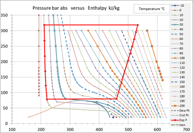
Carbon dioxide thermodynamic properties may be presented on a Mollier diagram providing pressure variation versus enthalpy for several temperature conditions. On this diagram, entropy and specific volume lines are also usually represented. See, for instance, Mollier diagram for carbon dioxide (R744) from http://frederic.benet.free.fr/.
The carbon dioxide geothermal loop operates under the following thermodynamic conditions:
The gas is firstly extracted from a reservoir through a production well. As the gas rises in the production well, the gas is expanded in an isentropic process (Temperature reduction).
At the surface, the gas is expanded in a turbine (an expander) providing mechanical energy. The gas expansion being carried out with some losses, this process is irreversible and called polytropic. It is characterised by an isentropic efficiency slightly lower than 1.
Before its re injection, the fluid is cooled down at constant pressure until it reaches the liquid or super critical condition. This is an isobaric process.
Following cooling, the fluid is re injected into the reservoir. As the fluid flows down, the pressure rises due to the monometric head without a significant change in the fluid temperature. This is an isothermal process.
In the reservoir, the fluid flows from the injection to the production wells receiving heat from the ambient media at a constant pressure. This is an isobaric process.
Carbon dioxide hydrate or carbon dioxide clathrate is a snow-like crystalline substance composed of water ice and carbon dioxide (It is normally a Type I gas clathrate). The clathrate formation occurs below approximately 283K (10 C). It is therefore important not to operate the geothermal loop and more particularly the injection well below 10 °C in order to avoid the formation of carbon dioxide hydrates and therefore the plugging of the injection well. See https://en.wikipedia.org/wiki/Carbon_dioxide_clathrate.
5_ Example of geothermal loop
An example of geothermal loop is described in the attached document (PDF).
It was studied based on the following operating conditions: Reservoir pressure and temperature, respectively, 319 bar abs and 180 °C; injection and production well length: 2 750 m; injection and production well diameter, respectively, 150 mm and 250 mm; carbon dioxide mass flow rate: 100 kg/s; expander isentropic efficiency: 85 %; expander discharge pressure: 80 bar abs; gas cooling before injection into the reservoir: 10°C (limit for hydrate formation).
The carbon dioxide leaves the reservoir with a pressure of 319 bar abs and a temperature of 180°C and reaches the surface with a pressure of 203 bar abs. Due to the gas expansion in the production well (pressure decrease), the temperature at the surface is reduced to 135°C. As an average, the gas volumetric mass in the production well is of the order of 400 kg/m3.
Through the expander, the gas is cooled down to 62 °C (57.6 °C for an isentropic expansion) then cooled in a final step by an external fluid down to 10°C. This provides a volumetric mass of 900 kg/m3 at the injection wellhead and of the order of 1000 kg/m3 at the bottom of the well. The wellhead pressure is 78 bar abs, i.e. 2 bar below the expander outlet pressure.
An isentropic expansion through the expander provides an energy unit of 43.2 kJ/kg. Applying an isentropic efficiency of 85 %, the energy provided by the expander is 36.7 kJ/kg. The heating rate dissipated during the final cooling process is 236 kJ/kg. The total heating rate transmitted by the reservoir to the gas is therefore 273 kW, the expander delivering only 13.4 % of that power. The thermodynamic operation of the motor cycle is represented on the Mollier diagram below.
6_ Parameter analysis
For details concerning the parameter analysis see the attached document (PDF).
6.1_ Post expansion cooling
Calculation has been carried out to determine the effect of the post cooling i.e. the temperature at the injection wellhead on the operation of the geothermal loop. This calculation has been performed for 10, 20 and 30 °C. In a general manner, the volumetric mass decreases in both the injection and the production well providing some sort of compensating effect.
The difference in performance is relatively small for post cooling temperatures of 10 and 20°C. In that instance, the production wellhead pressure is only reduced from 203 to 191 bar and the expander pressure ratio is only reduced from 1 / 2.54 to 1 / 2.39.
The effect of the post cooling becomes important above 20°C, particularly in the lower pressure sections of the injection and production wells. When the post cooling temperature is increased from 20 to 30°C, the expansion pressure ratio is reduced from 1 / 2.39 to 1 / 2.15. This corresponds to a significant reduction in the expander power supply.
6.2_ Expander outlet pressure
The case analysed in section 5 refers to an expander outlet pressure of 80 bar abs. This parameter was diminished to analyse its effect down to 46 bar where it approaches the dew point line. It has to be noted that this calculation was performed keeping constant the expander inlet conditions (199 bar abs and 135 °C).
By reducing this parameter from 80 bar, the energy per unit mass delivered by the expander increases significantly. The variation is relatively linear down to 60 bar below which the variation is quasi exponential.
The pressure at the injection wellhead decreases as the expander outlet pressure reduces. It is relatively small down to 60 bar becoming relatively important below that value. It is quasi exponential below 50 bar compromising the operation of the geothermal loop.
6.3_ Well pipe length
To evaluate the impact on the expander energy supply, injection and production pipe lengths have been increased by 20 % (from 2 750 to 3 300 m) keeping the reservoir temperature unchanged.
The pipe length being greater, the manometric head in the injection well is also greater. It is increased by 21 % (from 240 bar to 291 bar). Concerning the production well, the pipe length and the fluid volumetric mass (greater reservoir pressure) being both greater, the manometric head is also considerably greater. It is increased by 34 % (from 115 to 155 bar) while the differential temperature is increased by 19 % (from 44.8 to 53.5 °C) due to gas expansion from the reservoir to the surface.
At the expander inlet, the temperature is reduced from 135 (2 750 m) to 126.5°C (3 300 m).while the pressure ratio is increased from 1 / 2.49 to 1 / 2.63. As a result, the expander energy supply is increased by 14 %.
6.4_ Loop mass flow rate
Basic calculation has been performed with a mass flow rate of 100 kg/s but could be extended to any mass flow rate with some adaptation of the equipment and applying for some corrections, particularly, regarding energy losses. It has to be noted that the pipe diameters selected below do not correspond necessarily to a standard size.
For a 100 kg/s mass flow rate, equipment sizing does not present major difficulties (150 and 250 mm diameter for injection and production wells). The power provided by the expander is relatively small (isentropic 4.32 MW) by comparison with the residual heat (post cooling) which could present a major constraint if it cannot be exploited.
For a 1 000 kg/s mass flow rate (4 000 m3/hr at injection wellhead), the power provided by the expander is significant (isentropic 44 MW) and pipe diameters are still of a reasonable size (475 and 790 mm in this calculation). Same comment concerning post cooling.
For a 10 000 kg/s mass flow rate, the power provided by the expander is quite important (isentropic 460 MW) and the cooling duty is also hugged (2.36 GW – equivalent to two nuclear power plants). This case would require several injection and production wells located at a large distance from one another and an extended reservoir. This configuration could be of interest for a large urban area or number of inhabitants.
Pipe diameters have to be selected sufficiently large in order to minimize pressure losses in injection and production wells. If an injection well diameter was reduced by 20 %, the corresponding reservoir pressure would be reduced by 10 % and the column differential pressure by 14 % (to be considered as a limit). If a production well diameter was reduced by 30 %, the corresponding wellhead pressure would be reduced by 6 % and the column differential pressure would be increased by 9 % (to be considered as a limit). Beyond these diameter reductions, the operation of the geothermal loop would be compromised.
6.5_ Reservoir temperature
The calculation has been performed in two cases of reservoir temperature (180 and 150 °C) keeping constant the expander pressure ratio (approx. 1 / 2.48). Despite the expander pressure ratio was kept approximately constant, the power supplied by the expander is considerably reduced: 19.9 MW instead of 36.7 MW (46 % less) by reducing the reservoir temperature from 180 to 150°C. The expander energy relative to the post cooling duty is also reduced: 13.4 % in the hot case and 9.6 % in the cold case.
This highlights the importance of the reservoir temperature.
Concerning the parameter analysis, further details may be found in the following document (PDF).

7_ Secondary circuit
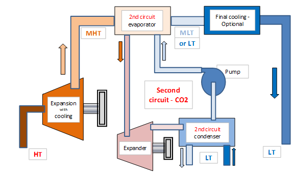
Section 5 indicates that energy of 43.2 kJ/kg and residual heat of 236 kJ/kg may be extracted for every mass unit of produced carbon dioxide. These energy and heat are obtained for inlet and outlet pressures, of respectively, 199 and 80 bar abs and an inlet temperature of 135°C (“HT” on figure below). Based on an isentropic efficiency of 85 %, the outlet temperature is 62 °C (“MHT”). The residual heat is therefore available at this relatively high temperature.
The process fluid is cooled down before its reinjection into the storage reservoir. It has been shown in section 6.1 that the efficiency of the geothermal loop is reduced by 6.4 % by increasing the injection temperature from 10 °C to 20 °C (17 % in the case of 30 °C).
It is assumed in the following that a cooling media is available at a relatively low temperature. Consequently, these two heat sources at a different temperature may be used to activate a motor cycle (“Secondary circuit”). The efficiency of the motor cycle is dependent on the temperature difference. As an example, for a 10°C cold source, the Carnot efficiency is 15 %. Calculations have been performed with cold sources of plus 6.8 and minus 6.8 °C.
The motor cycle includes an evaporator, an expander, a pump, a condenser and a refrigerant flowing in that order. From the evaporator, the refrigerant removes heat from the main fluid (inlet temperature 60 °C). Operating the motor cycle at a relatively high pressure (80 bars in the present case) the refrigerant enters into the expander where gas expansion occurs producing energy and cooling. At its outlet, the gas enters into the condenser where it is cooled by an external media and liquefied. At the condenser outlet, the liquid is pressurised to the evaporator pressure to initiate another refrigerant cycle.
_
Cooling media between 10 and 20 °C
Temperature at this level may be encountered in many circumstances: atmospheric air, aquifers, water from the sea surface (cold or temperate seas) or pumped from the thermocline in the case of tropical seas. Calculations have not been performed in that temperature range but some order of magnitude may be deduced from the theoretical Carnot efficiency values (See PDF) and the two calculations performed below at two low temperatures: plus 6.8 and minus 6.8°C. It has to be noted that the Carnot efficiency is relatively proportional to the hot and cold temperature difference.
Calculations have been performed using the CoolPack software developed by the Department of Mechanical Engineering (MEK), Section of Thermal Energy (TES) at the Technical University of Denmark (DTU).
Cooling media at plus 6.8 °C
The cycle is operated with pure carbon dioxide in order to avoid the formation of hydrates (temperature below 10°C). The “2nd circuit” expander operates with inlet pressure and temperature of, respectively, 80 bar abs and 60°C and an outlet pressure of 40 bar abs corresponding to an outlet temperature of 6.9°C close to the dew point line.
The “2nd circuit” absorbs the heat (236 kJ/kg) provided by the process fluid through the evaporator while the expander supplies 22.0 kJ/kg (pumping energy taken into account) and releases the rest of the heat through the condenser. For a Carnot efficiency of 16 %, actual efficiency is 9.3%. This energy represents 51 % of the main expander energy. Calculation was performed with a cooling temperature of 6.8 °C. This indicates that an extra cooling is required or that this cooling is permitted only for reduced periods of time (seasonal conditions) or in specific areas (case of North Sea – Sea temperature often close to 4°C).
The study has been performed only with pure carbon dioxide. Other refrigerant fluids could be investigated to evaluate their respective benefit.
To get further details concerning operation of the motor cycle at 6.8 °C and minus 6.8 °C see the attached document (PDF).
8_ Merging main and secondary circuits
This case is briefly discussed in the attached document. There are some reservoir conditions where the energy of the main expander is significantly lower than the one of the secondary circuit. In that case, it may be preferable to use a single expansion system: the secondary circuit one.
9_ Conclusion
A geothermal loop may be operated with carbon dioxide without any pressurizing equipment. To the contrary, a geothermal loop may produce mechanical energy when site conditions are present. This energy is accompanied with a significant amount of heat.
The large difference in manometric heads between the injection well, characterized by a large volumetric mass of the fluid (of the order of 1 000 kg/m3) and the production well, characterized by a medium volumetric mass of the fluid (of the order of 400 kg/m3) permits the operation of a geothermal loop due to the existence of a large pressure difference between the two wells.
The efficiency of the geothermal loop increases with the reservoir temperature, the reservoir pressure and the well length. This indicates that only specific areas are suitable for producing heat and energy in an efficient way. If only heat is required, the application field of the technology is considerably wider.
Calculations in different reservoir configurations indicate that 10 to 15 % of the capted reservoir heat may be converted into mechanical energy.
The residual heat may be used to provide heating to residential areas if they are present in close vicinity. If it is not the case, a fraction of that heat may be converted to mechanical energy in a second motor cycle circuit. The efficiency of that loop is of the order of 10 % (approximately 50 to 60 % of the Carnot efficiency). The operation of the second circuit was analysed with pure carbon dioxide operating at low temperature (around 0°C, only available in specific areas or for reduced time intervals). It is possible that this second circuit would operate more efficiently with another refrigerant. This may be tested in a near future. As an overall, the main geothermal loop and the second motor cycle circuit may convert 15 to 20% of the capted heat into mechanical energy.
This study was performed by Yves CHARRON in 2020. For any question use form below:
http://yvcharron.com/index.php/contact/ or